ESP32-S3-Korvo-2 V3.0
This user guide will help you get started with ESP32-S3-Korvo-2 V3.0 and will also provide more in-depth information.
The ESP32-S3-Korvo-2 is a multimedia development board based on the ESP32-S3 chip. It is equipped with a two-microphone array which is suitable for voice recognition and near/far-field voice wake-up applications. The board integrates multiple peripherals such as LCD, camera, and microSD card. It also supports JPEG video stream processing. With all of its outstanding features, the board is an ideal choice for the development of low-cost and low-power network-connected audio and video products.
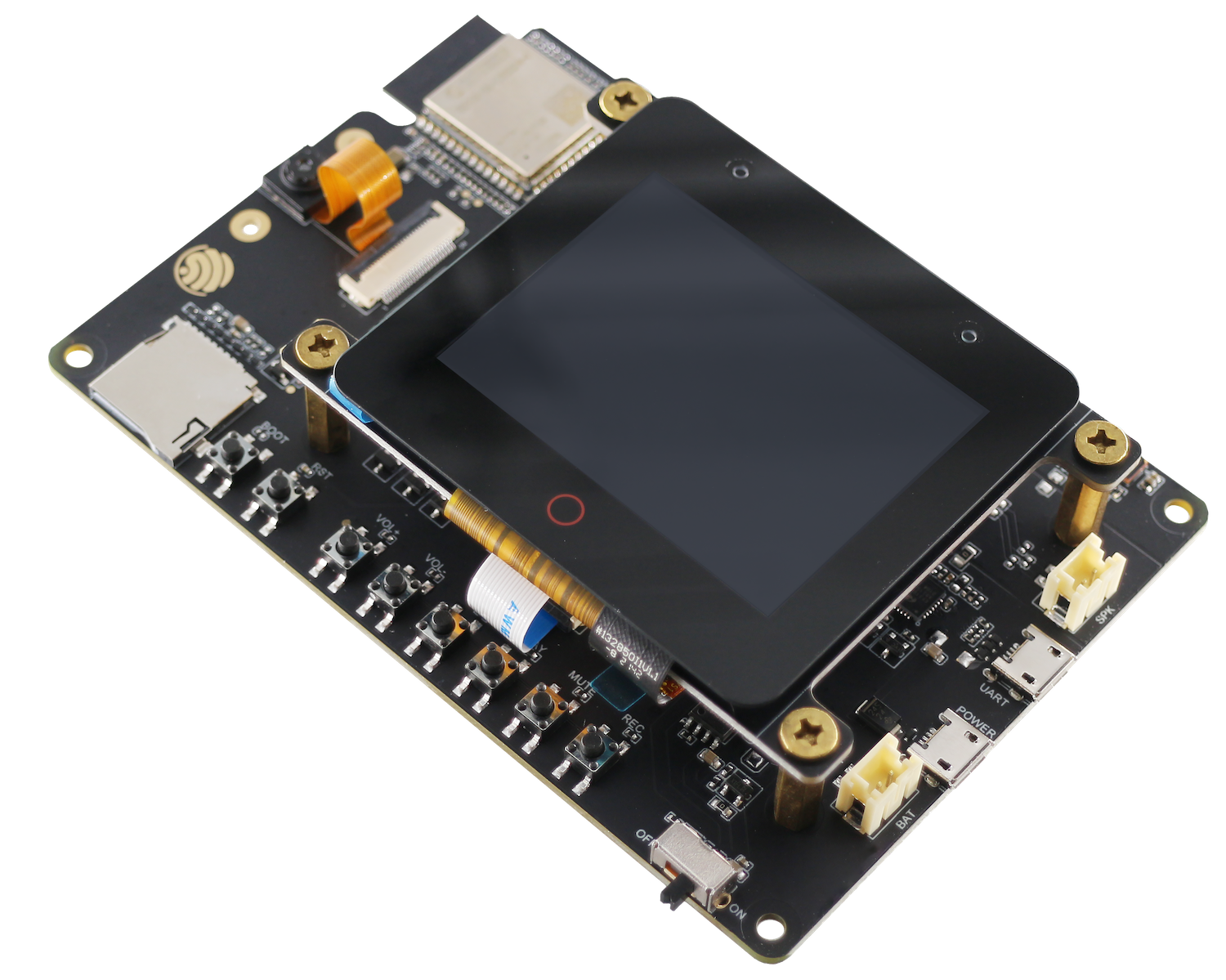
ESP32-S3-Korvo-2 V3.0 with ESP32-S3-WROOM-1 module
This board mainly consists of the following parts:
Main board: ESP32-S3-Korvo-2
LCD extension board: ESP32-S3-Korvo-2-LCD
Camera
This document is mostly dedicated to the main board. For detailed information on other parts, click the links above.
The document consists of the following sections:
Getting started: Overview of the board and hardware/software setup instructions to get started.
Hardware Reference: More detailed information about the board’s hardware.
Hardware Revision Details: Hardware revision history, known issues, and links to user guides for previous versions (if any) of the board.
Related Documents: Links to related documentation.
Getting Started
This section provides a brief introduction of ESP32-S3-Korvo-2 V3.0, instructions on how to do the initial hardware setup and how to flash firmware onto it.
Description of Components
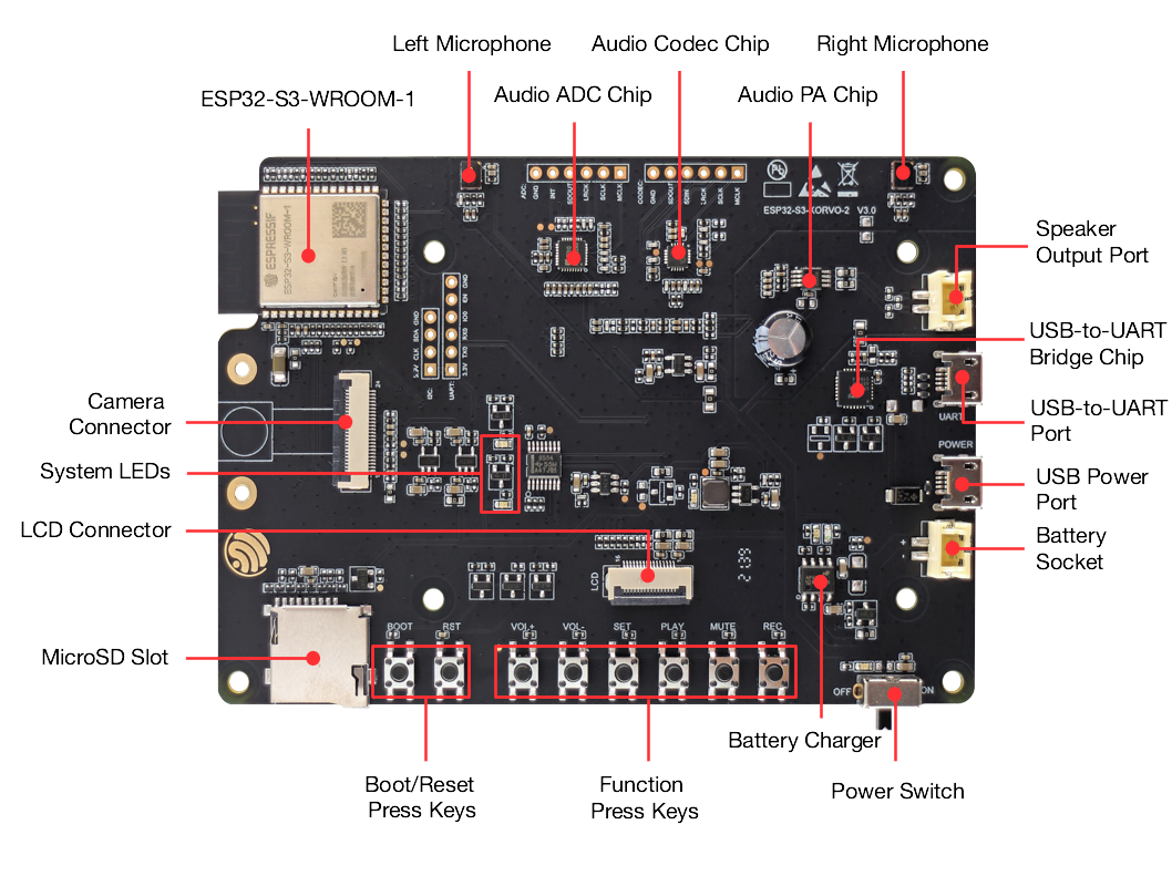
ESP32-S3-Korvo-2 V3.0 (click to enlarge)
The key components of the board are described in a clockwise direction.
Key Component |
Description |
|---|---|
ESP32-S3-WROOM-1 Module |
The ESP32-S3-WROOM-1 is a powerful, generic Wi-Fi + Bluetooth LE MCU module that is built around the ESP32-S3 series of SoCs. On top of a rich set of peripherals, the acceleration for neural network computing and signal processing workloads provided by the SoC make the modules an ideal choice for a wide variety of application scenarios related to AI and Artificial Intelligence of Things (AIoT), such as wake word detection, speech commands recognition, face detection and recognition, smart home, smart appliances, smart control panel, smart speaker, etc. |
Left Microphone |
Onboard microphone connected to ADC. |
Audio ADC Chip |
ES7210 is a high-performance, low-power 4-channel audio analog-to-digital converter for microphone array applications. It is very suitable for music and speech applications. In addition, ES7210 can also be used to collect acoustic echo cancellation (AEC) echo reference signals. |
Audio Codec Chip |
The audio codec chip, ES8311, is a low-power mono audio codec. It consists of 1-channel ADC, 1-channel DAC, low noise pre-amplifier, headphone driver, digital sound effects, analog mixing, and gain functions. It is interfaced with ESP32-S3-WROOM-1 module over I2S and I2C buses to provide audio processing in hardware independently from the audio application. |
Audio PA Chip |
NS4150 is an EMI, 3 W mono Class D audio power amplifier, amplifying audio signals from audio codec chips to drive speakers. |
Right Microphone |
Onboard microphone connected to ADC. |
Speaker Output Port |
Output socket to connect a speaker. The 4-ohm and 3-watt speaker is recommended. The pins have a 2.00 mm/0.08” pitch. |
USB-to-UART Bridge Chip |
A single chip USB-UART bridge CP2102N provides up to 3 Mbps transfer rates for software download and debugging. |
USB-to-UART Port |
Functions as the communication interface between a PC and the ESP32-S3-WROOM-1 module. |
USB Power Port |
Provides power to the board. It is recommended to use at least 5V/2A power adapter to ensure a stable power supply. |
Battery Socket |
Two pins socket to connect a single cell Li-ion battery. |
Power Switch |
Power on/off knob: toggling it down powers the board on; toggling it up powers the board off. |
Battery Charger |
AP5056 is a constant current and constant voltage linear charger for single cell lithium-ion batteries. Used for charging of a battery connected to the Battery Socket over the Micro USB Port. |
Function Press Keys |
Six press keys labeled REC, MUTE, PLAY, SET, VOL- and VOL+. They are routed to ESP32-S3-WROOM-1 module and intended for development and testing of a UI for audio applications using a dedicated API. |
Boot/Reset Press Keys |
Boot: holding down the Boot key and momentarily pressing the Reset key initiates the firmware upload mode. Then you can upload firmware through the serial port.
Reset: pressing this button alone resets the system.
|
MicroSD Slot |
The development board supports a microSD card in 1-bit mode, and can store or play audio files in the microSD card. |
LCD Connector |
A FPC connector with 0.5 mm pitch to connect to the LCD extension board. |
System LEDs |
Two general-purpose LEDs (green and red) controlled by ESP32-S3-WROOM-1 module to indicate certain operation states of the audio application using dedicated API. |
Camera Connector |
An external camera module that can be connected to the development board with the connector to transmit images. |
Start Application Development
Before powering up your board, please make sure that it is in good condition with no obvious signs of damage.
Required Hardware
1 x ESP32-S3-Korvo-2 V3.0
1 x Speaker
2 x USB 2.0 cable (Standard-A to Micro-B)
1 x Computer running Windows, Linux, or macOS
Note
Be sure to use an appropriate USB cable. Some cables are for charging only and do not provide the needed data lines nor work for programming the boards.
Optional Hardware
1 x MicroSD card
1 x Li-ion battery
Note
Be sure to use a Li-ion battery that has a built-in protection circuit.
Hardware Setup
Connect the speaker to the Speaker Output.
Plug in the USB cables to the PC and to both USB ports of the board.
The standby LED (green) should turn on. Assuming that a battery is not connected, the charging LED (red) will blink every couple of seconds.
Toggle the Power Switch.
The red Power On LED should turn on.
Software Setup
Please proceed to Get Started, where Section Installation Step by Step will quickly help you set up the development environment and then flash an application example onto your board.
Contents and Packaging
The main board and its accessories can be ordered separately. The accessories include:
LCD extension board: ESP32-S3-Korvo-2-LCD
Camera
Connectors:
20-pin FPC cable
Fasteners:
Copper standoffs (x8)
Screws (x4)
Retail Orders
If you order a few samples, each board comes in an individual package in either antistatic bag or any packaging depending on your retailer.
For retail orders, please go to https://www.espressif.com/en/company/contact/buy-a-sample.
Wholesale Orders
If you order in bulk, the boards come in large cardboard boxes.
For wholesale orders, please go to https://www.espressif.com/en/contact-us/sales-questions.
Hardware Reference
Block Diagram
The block diagram below shows the components of ESP32-S3-Korvo-2 V3.0 and their interconnections.
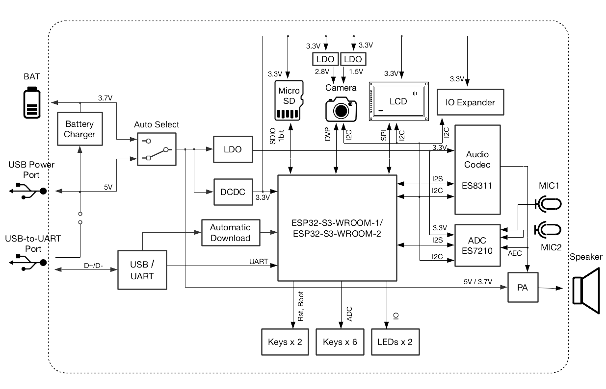
ESP32-S3-Korvo-2 V3.0 Electrical Block Diagram
Notes on Power Distribution
Power Supply over USB and from Battery
The main power supply is 5 V and provided by a USB. The secondary power supply is 3.7 V and provided by an optional battery. The USB power itself is fed with a dedicated cable, separating from a USB cable used for an application upload. To further reduce noise from the USB, the battery may be used instead of the USB.
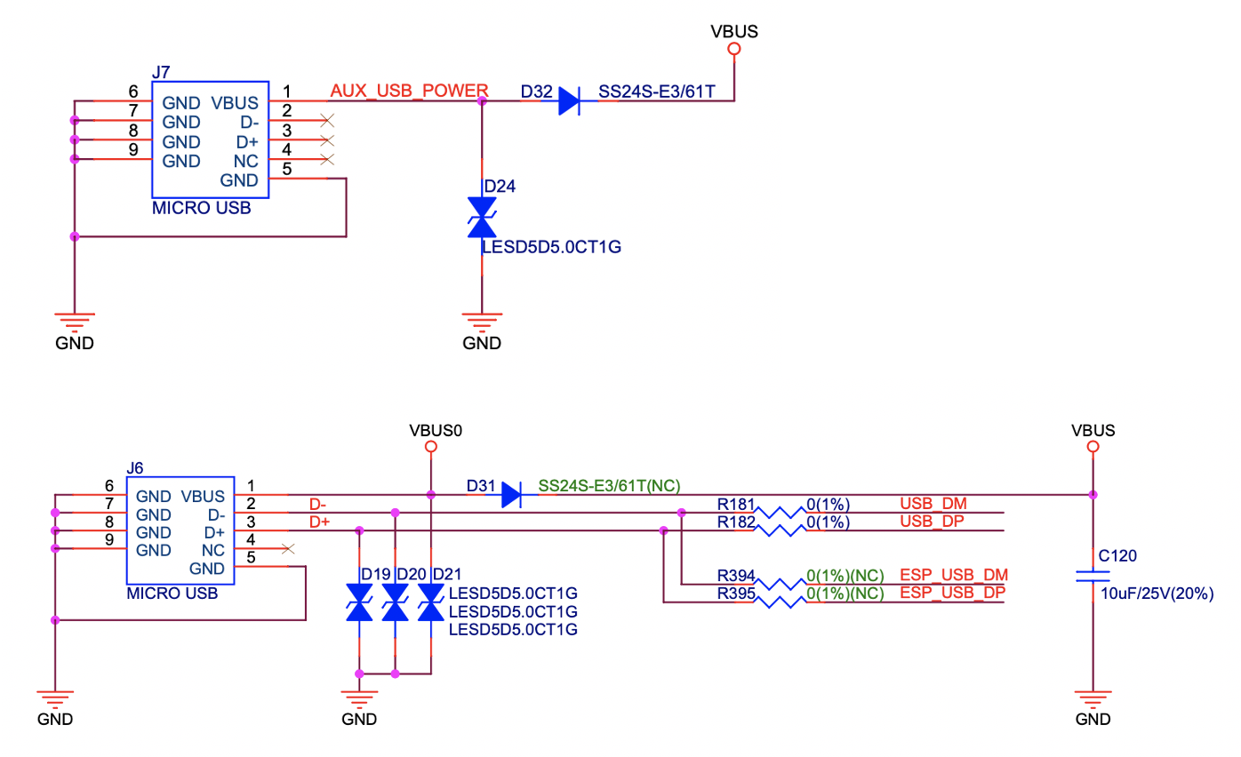
ESP32-S3-Korvo-2 V3.0 - Dedicated USB Power Supply Socket
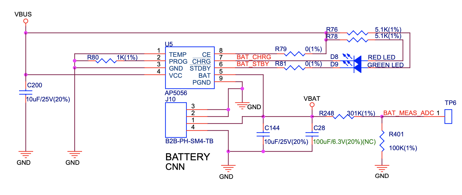
ESP32-S3-Korvo-2 V3.0 - Power Supply from a Battery
As shown in the figure below, if the USB power supply and battery power supply are connected at the same time with a high VBUS, an off-state Q14, and an automatic cut-off VBAT, the USB becomes the power supply for the system.
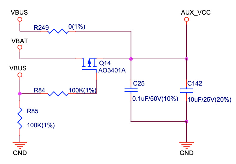
ESP32-S3-Korvo-2 V3.0 - Power Supply Options
Independent Audio and Digital Power Supply
ESP32-S3-Korvo-2 V3.0 features independent power supplies to the audio components and ESP module. This should reduce noise in the audio signal from digital components and improve overall performance of the components.
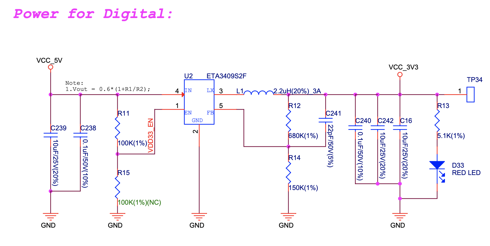
ESP32-S3-Korvo-2 V3.0 - Digital Power Supply
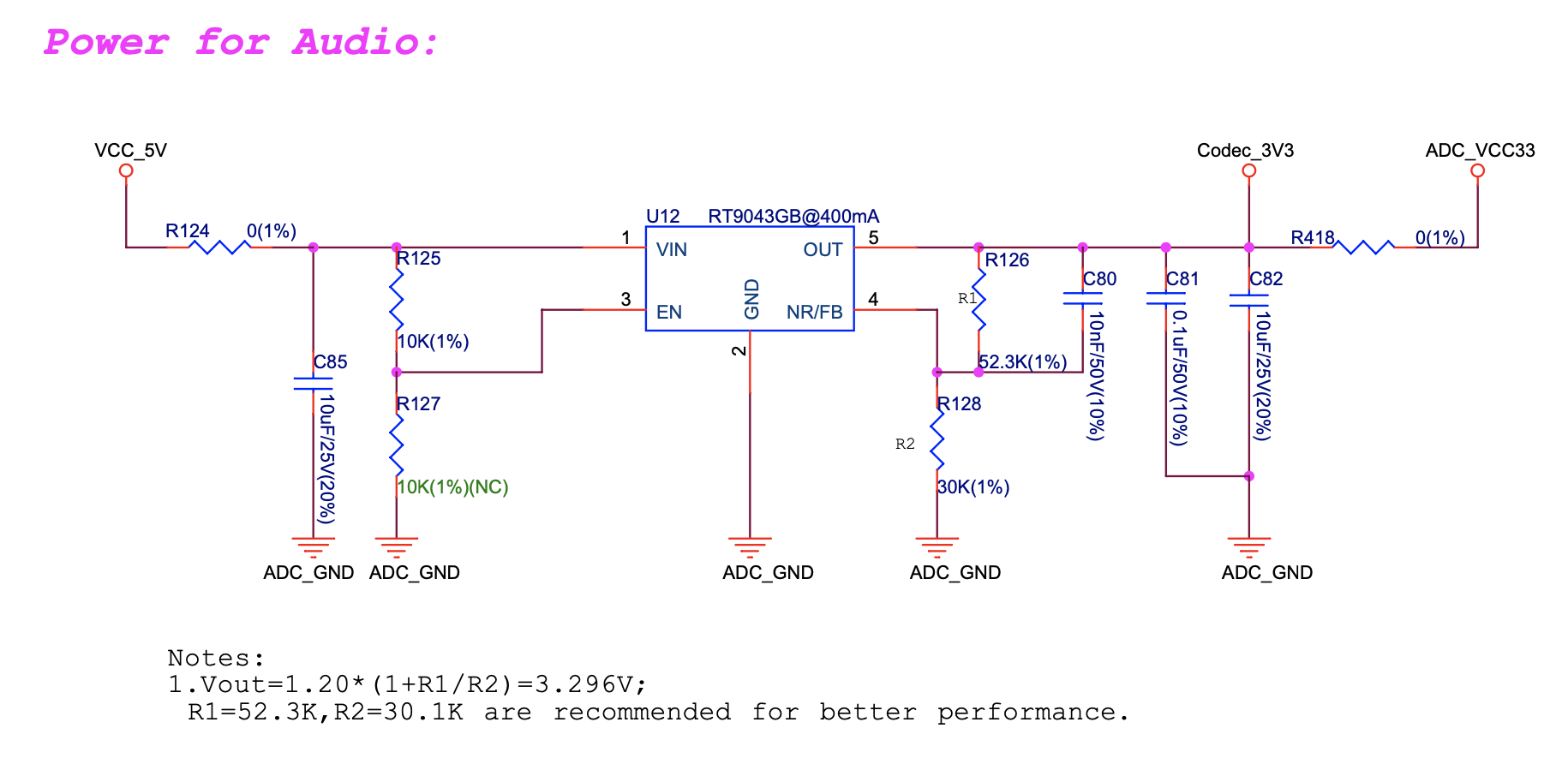
ESP32-S3-Korvo-2 V3.0 - Audio Power Supply
GPIO Allocation Summary
The table below provides allocation of GPIOs exposed on terminals of ESP32-S3-WROOM-1 module to control specific components or functions of the board.
Pin 1 |
Pin Name |
ES8311 |
ES7210 |
Camera |
LCD |
Keys |
MicroSD |
IO Expander |
Other |
|---|---|---|---|---|---|---|---|---|---|
3 |
EN |
EN_KEY |
|||||||
4 |
IO4 |
DATA0 |
|||||||
5 |
IO5 |
REC, MUTE, PLAY, SET, VOL-, VOL+ |
|||||||
6 |
IO6 |
BAT_MEAS_ADC |
|||||||
7 |
IO7 |
CMD |
|||||||
8 |
IO15 |
CLK |
|||||||
9 |
IO16 |
I2S0_MCLK |
MCLK |
||||||
10 |
IO17 |
I2C_SDA |
I2C_SDA |
SIOD |
TP_I2C_SDA |
I2C_SDA |
|||
11 |
IO18 |
I2C_CLK |
I2C_CLK |
SIOC |
TP_I2C_CLK |
I2C_CLK |
|||
12 |
IO8 |
I2S0_DSDIN |
|||||||
13 |
IO19 |
ESP_USB_DM (Reserve) |
|||||||
14 |
IO20 |
ESP_USB_DP (Reserve) |
|||||||
15 |
IO3 |
D5 |
|||||||
16 |
IO46 |
NC |
|||||||
17 |
IO9 |
I2S0_SCLK |
SCLK |
||||||
18 |
IO10 |
SDOUT |
|||||||
19 |
IO11 |
PCLK |
|||||||
20 |
IO12 |
D6 |
|||||||
21 |
IO13 |
D2 |
|||||||
22 |
IO14 |
D4 |
|||||||
23 |
IO21 |
VSYNC |
|||||||
24 |
IO47 |
D3 |
|||||||
25 |
IO48 |
PA_CTRL |
|||||||
26 |
IO45 |
I2S0_LRCK |
LRCK |
||||||
27 |
IO0 |
LCD_SPI_SDA |
BOOT_KEY |
||||||
28 |
IO35 |
NC |
|||||||
29 |
IO36 |
NC |
|||||||
30 |
IO37 |
NC |
|||||||
31 |
IO38 |
HREF |
|||||||
32 |
IO39 |
D9 |
|||||||
33 |
IO40 |
XCLK |
|||||||
34 |
IO41 |
D8 |
|||||||
35 |
IO42 |
D7 |
|||||||
36 |
RXD0 |
ESP0_UART0_RX |
|||||||
37 |
TXD0 |
ESP0_UART0_TX |
|||||||
38 |
IO2 |
LCD_SPI_DC |
|||||||
39 |
IO1 |
LCD_SPI_CLK |
|||||||
41 |
EPAD |
- 1
Pin - ESP32-S3-WROOM-1 module pin number, GND and power supply pins are not listed.
The GPIOs allocated to the IO expander are further expanded to multiple GPIOs.
IO Expander Pin |
Pin Name |
LCD |
Other |
|---|---|---|---|
4 |
P0 |
PA_CTRL |
|
5 |
P1 |
LCD_CTRL |
|
6 |
P2 |
LCD_RST |
|
7 |
P3 |
LCD_CS |
|
9 |
P4 |
TP_INT |
|
10 |
P5 |
PERI_PWR_ON |
|
11 |
P6 |
LED1 |
|
12 |
P7 |
LED2 |
Connector
Camera Connector
No. |
Camera Signal |
ESP32-S3 Pin |
|---|---|---|
1 |
SIOD |
GPIO17 |
2 |
SIOC |
GPIO18 |
3 |
D5 |
GPIO3 |
4 |
PCLK |
GPIO11 |
5 |
D6 |
GPIO12 |
6 |
D2 |
GPIO13 |
7 |
D4 |
GPIO14 |
8 |
VSYNC |
GPIO21 |
9 |
D3 |
GPIO47 |
10 |
HREF |
GPIO38 |
11 |
D9 |
GPIO39 |
12 |
XCLK |
GPIO40 |
13 |
D8 |
GPIO41 |
14 |
D7 |
GPIO42 |
LCD Connector
No. |
LCD Signal |
ESP32-S3 Pin |
|---|---|---|
1 |
TP_I2C_SDA |
GPIO17 |
2 |
TP_I2C_CLK |
GPIO18 |
3 |
LCD_SPI_SDA |
GPIO0 |
4 |
LCD_SPI_DC |
GPIO2 |
5 |
LCD_SPI_CLK |
GPIO1 |
No. |
LCD Signal |
IO Expander |
|---|---|---|
1 |
ESP_LCD_CTRL |
P1 |
2 |
ESP_LCD_RST |
P2 |
3 |
ESP_LCD_CS |
P3 |
4 |
ESP_TP_INT |
P4 |
AEC Path
AEC path provides reference signals for AEC algorithm.
ESP32-S3-Korvo-2 provides two compatible echo reference signal source designs. One is Codec (ES8311) DAC output (DAC_AOUTLN/DAC_AOUTLP), the other is PA (NS4150) output (PA_OUTL+/PA_OUTL-). The former is the default and recommended selection. Resistors R132 and R140 marked NC (no component) in the figure below should not be installed.
The echo reference signal is collected by ADC_MIC3P/ADC_MIC3N of ADC (ES7210) and then sent back to ESP32-S3 for AEC algorithm.
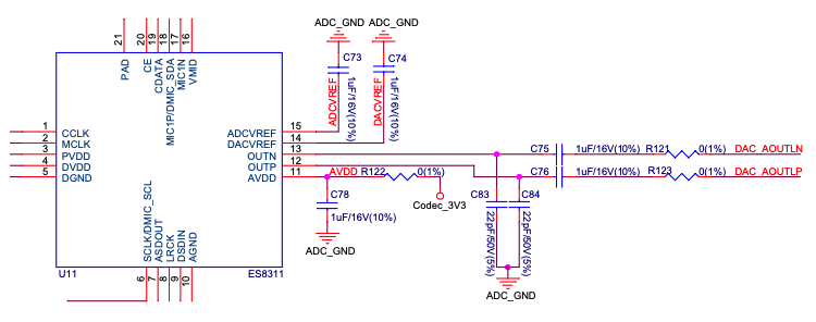
ESP32-S3-Korvo-2 V3.0 - AEC Codec DAC Output (click to enlarge)
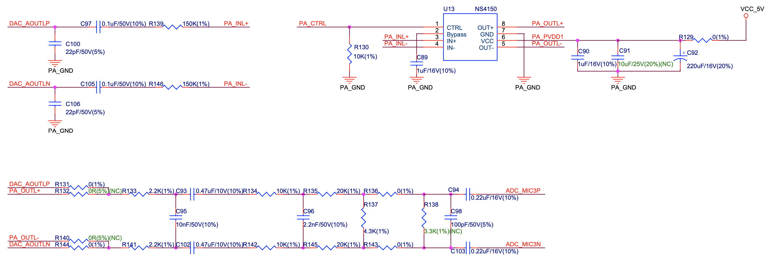
ESP32-S3-Korvo-2 V3.0 - AEC PA Output (click to enlarge)
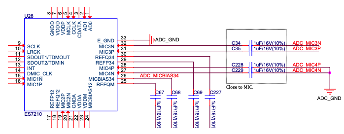
ESP32-S3-Korvo-2 V3.0 - AEC Reference Signal Collection (click to enlarge)
Hardware Setup Options
Using Automatic Upload
Entering of the ESP board into upload mode may be done in two ways:
Manually by pressing both Boot and RST keys and then releasing first RST and then Boot key.
Automatically by software performing the upload. The software is using DTR and RTS signals of the serial interface to control states of EN and IO0 of the ESP board. For details see ESP32-S3-Korvo-2 V3.0 Schematic (PDF).
Allocation of ESP Pins to Test Points
This section describes the allocation of test points available on the ESP32-S3-Korvo-2 V3.0 board.
The test points are bare through hole solder pads and have a standard 2.54 mm/0.1” pitch. You may need to populate them with pin headers or sockets for easy connection of external hardware.
Codec Test Point/J15
No. |
Codec Pin |
ESP32-S3 Pin |
|---|---|---|
1 |
MCLK |
GPIO16 |
2 |
SCLK |
GPIO9 |
3 |
LRCK |
GPIO45 |
4 |
DSDIN |
GPIO8 |
5 |
ASDOUT |
– |
6 |
GND |
– |
ADC Test Point/J16
No. |
ADC Pin |
ESP32-S3 Pin |
|---|---|---|
1 |
MCLK |
GPIO16 |
2 |
SCLK |
GPIO9 |
3 |
LRCK |
GPIO45 |
4 |
SDOUT |
GPIO10 |
5 |
INT |
– |
6 |
GND |
– |
UART Test Point/J17
No. |
UART Pin |
|---|---|
1 |
3.3V |
2 |
TXD |
3 |
RXD |
4 |
IO0 |
5 |
EN |
6 |
GND |
I2C Test Point/J18
No. |
I2C Pin |
ESP32-S3 Pin |
|---|---|---|
1 |
3.3V |
– |
2 |
CLK |
GPIO18 |
3 |
SDA |
GPIO17 |
4 |
GND |
– |
Hardware Revision Details
This is the first revision of this board released.