ESP32-C3-Lyra V2.0
This user guide will help you get started with ESP32-C3-Lyra V2.0 and will also provide more in-depth information.
The document consists of the following sections:
Board Overview: Overview of the board hardware/software.
Start Application Development: How to set up hardware/software to develop applications.
Hardware Reference: More detailed information about the board’s hardware.
Hardware Revision Details: Hardware revision history, known issues, and links to user guides for previous versions (if any) of the board.
Ordering: How to buy the board.
Related Documents: Links to related documentation.
Board Overview
ESP32-C3-Lyra is an ESP32-C3-based audio development board produced by Espressif for controlling light with audio. The board has control over the microphone, speaker, and LED strip, perfectly matching customers’ product development needs for ultra-low-cost and high-performance audio broadcasters and rhythm light strips.
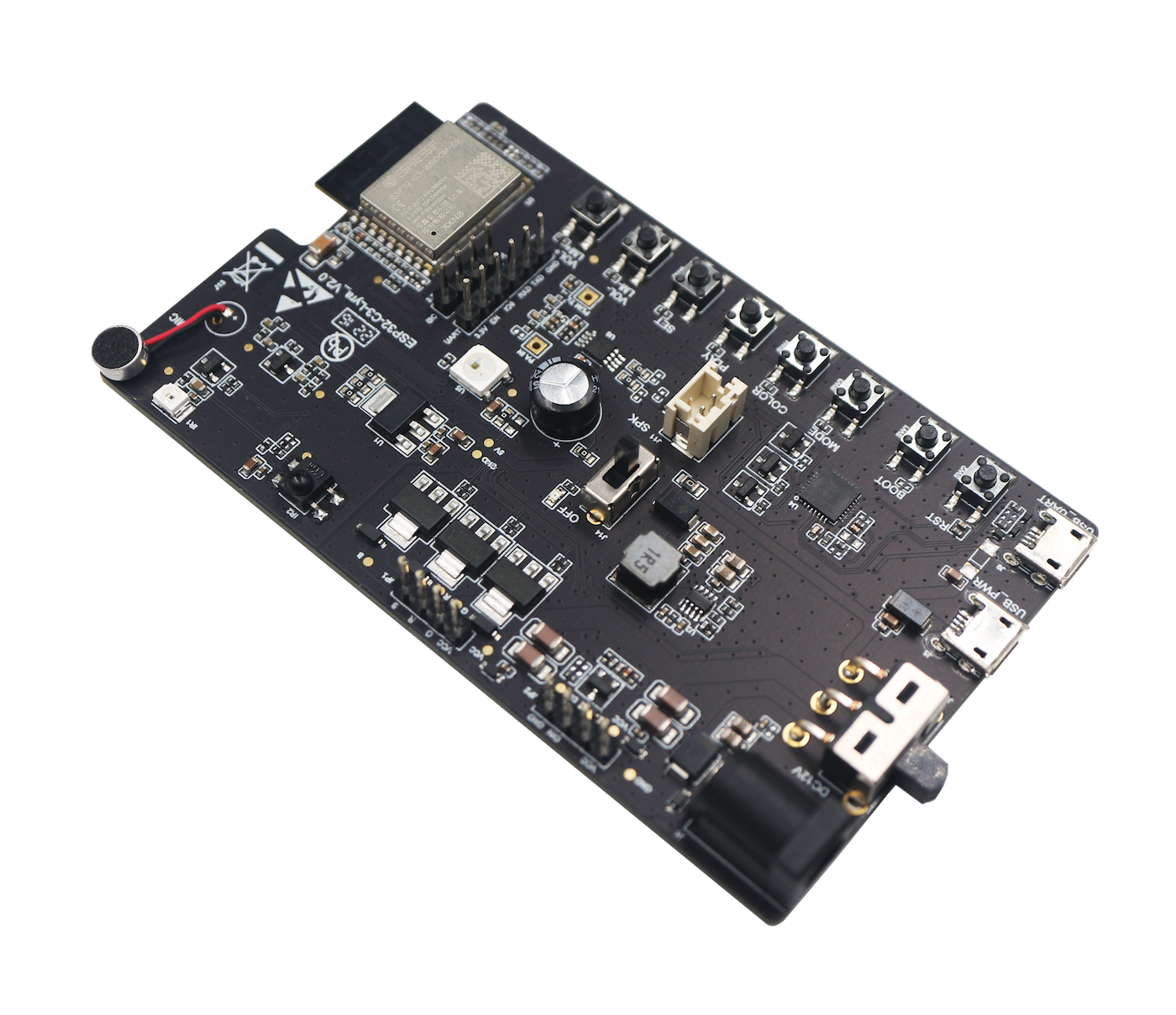
ESP32-C3-Lyra with ESP32-C3-WROOM-02 module
Feature List
The main features of the board are listed below:
Module Embedded: ESP32-C3-WROOM-02 module with a 4 MB external SPI flash
Audio: built-in ECM microphone, speaker power amplifier, speaker connector
LED Strip Connector: support for two types of connections, i.e., connections to addressable LED strips and RGB LED strips
Infrared Control: support for infrared (IR) transmitting and receiving
Keys: boot key, reset key, and six function keys (MODE, COLOR, PLAY/PAUSE, SET, VOL+/LM+, VOL-/LM-)
USB: 1 x USB Power Port, 1 x USB-to-UART Port
Power Supply: 5 V power supply over USB or 12 V DC power supply
Block Diagram
The block diagram below shows the components of ESP32-C3-Lyra and their interconnections.
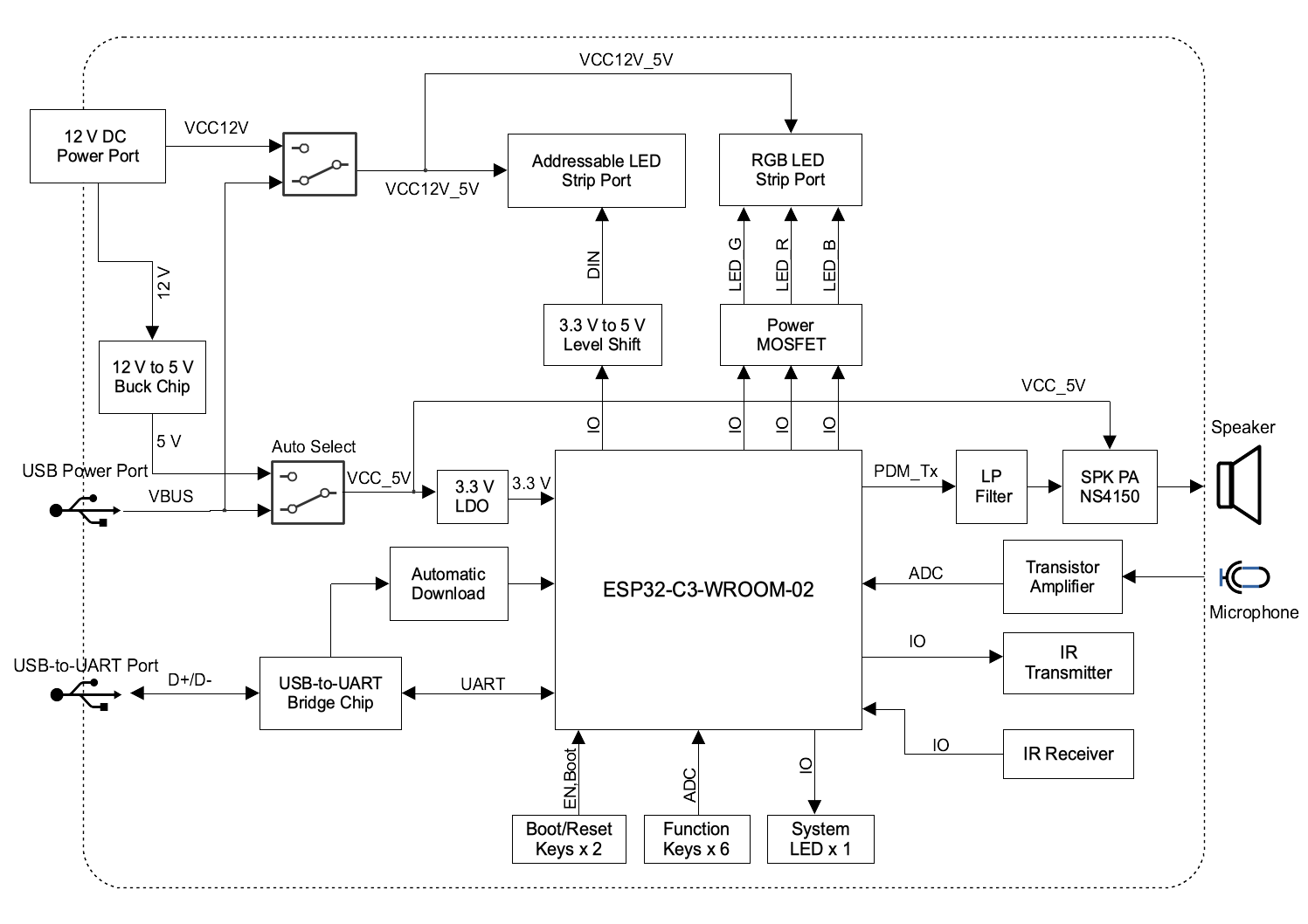
ESP32-C3-Lyra Block Diagram (click to enlarge)
Description of Components
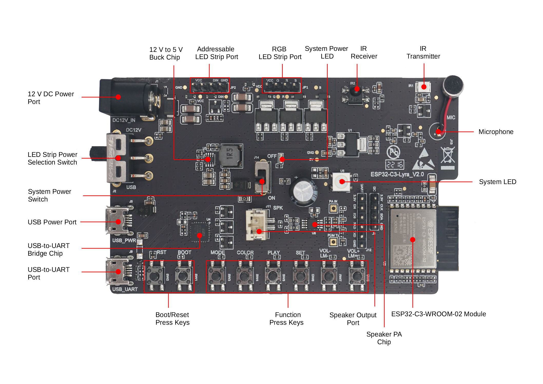
ESP32-C3-Lyra - front (click to enlarge)
The key components of the board are described in a clockwise direction.
Key Component |
Description |
|---|---|
ESP32-C3-WROOM-02 Module |
It is a general-purpose Wi-Fi and Bluetooth LE module developed based on ESP32-C3, a 32-bit RISC-V single-core processor that operates at up to 160 MHz. The module has a rich set of peripherals and a high performance, making it an ideal choice for smart homes, industrial automation, health care, consumer electronics, etc. It integrates a 4 MB external SPI flash and an on-board PCB antenna. The ESP32-C3-WROOM-02U module is also compatible with this board, but it needs to connect to an external antenna. |
Speaker PA Chip |
NS4150 is an EMI, 3 W mono Class D audio power amplifier, amplifying audio signals from ESP32-C3 PDM_TX to drive speakers. |
Speaker Output Port |
Output socket to connect a speaker. The 4-ohm and 3-watt speaker is recommended. The pins have a 2.00 mm/0.08” pitch. |
Function Press Keys |
Six function press keys, including MODE, COLOR, PLAY/PAUSE, SET, VOL+/LM+, VOL-/LM-. They are routed to the ESP32-C3-WROOM-02 Module and intended for the development and testing of a UI for audio applications or LED strips using dedicated APIs. |
Boot/Reset Press Keys |
Boot: holding down the Boot key and momentarily pressing the Reset button initiates the firmware upload mode. Then you can upload firmware through the serial port. Reset: pressing this key alone resets the system. |
USB-to-UART Port |
Functions as the communication interface between the PC and the ESP32-C3-WROOM-02 module. |
USB-to-UART Bridge Chip |
The single-chip USB-UART bridge CP2102N provides up to 3 Mbps transfer rates for software download and debugging. |
USB Power Port |
Provides power to the board. It is recommended to use at least 5 V/2 A power adapters to ensure a stable power supply. |
System Power Switch |
System Power on/off knob. Toggling it to ON turns the 5 V system power on; toggling it to OFF turns the 5 V system power off. |
LED Strip Power Selection Switch |
Toggle this switch to select between a 5 V power supply over USB and a 12 V DC power supply for your LED strip according to the working voltage of the LED strip and the type of the power adapter you actually use. |
12 V DC Power Port |
Supports 12 V DC power adapters with a maximum current of 2 A. The DC power Jack contact have an outer diameter of 5.5 mm and an inner contact diameter of 2.5 mm. |
12 V to 5 V Buck Chip |
The 12 V to 5 V buck chip MP2313 is a high-efficiency synchronous step-down converter that operates at 1 A and 2 MHz. |
Addressable LED Strip Port |
It is a male pin header connector with 4 x 1 pins and a 2.54 mm pitch. It can connect to the addressable LED strip that is controlled with a single wire. It supports 5 V and 12 V LED strips, such as WS2811 and WS2812 LED. ESP32-C3 can send commands to control the LED strips over RMT or SPI. |
RGB LED Strip Port |
It is a male pin header connector with 4 x 1 pins and a 2.54 mm pitch. It can connect to regular RGB LED strips (non-addressable, individual wire per color) that operate at 5 V or 12 V. ESP32-C3 can output PWM waveform via this port to control the LED strips. |
System Power LED |
It turns red when System Power Switch is toggled to ON. |
IR Receiver |
IRM-H638T/TR2 is a miniature SMD type infrared remote control system receiver. The demodulated output signal can directly be decoded by ESP32-C3. |
IR Transmitter |
IR67-21C/TR8 is an infrared emitting diode. It is spectrally matched with silicon photodiode and phototransistor. |
Microphone |
On-board ECM microphone. Signals picked up by it are amplified via transistors and sent to the analog-to-digital converter (ADC) of ESP32-C3-WROOM-02. |
System LED |
It is an RGB LED, model WS2812C, controlled by the ESP32-C3-WROOM-02 via GPIO, which can be used to indicate the operating status of the audio application. |
Default Firmware and Function Test
Each ESP32-C3-Lyra comes with a pre-built default firmware that allows you to test its functions including LED control (LEDC), remote control transceiver (RMT), ADC, and pulse-density modulation (PDM_TX). This section describes how to test peripheral’s function with the pre-built firmware.
Note
The default firmware of ESP32-C3-Lyra sold in the Developing IoT Projects with ESP32-C3 Package II provides a musical rhythm light ring effect.
Preparing Hardware
See Section Required Hardware and Optional Hardware for more information.
1 x ESP32-C3-Lyra
2 x USB 2.0 cable (Standard-A to Micro-B)
1 x Computer running Windows, Linux, or macOS
1 x 5 V RGB LED strip WS2812 (optional)
1 x Mobile phone or music player
1 x Speaker (optional)
Connecting Hardware
Before powering up your board, please make sure that it is in good condition with no obvious signs of damage.
Connect the board to the 5 V power supply through the USB Power Port using a USB cable. After the board is powered up, you will notice that the System Power LED turns on, which means the board is powered up. If the LED is not on, please toggle the System Power Switch.
Toggle the LED Strip Power Selection Switch to the USB power side.
Connect the board to the computer through the USB-to-UART Port using a USB cable.
Testing Default Firmware
Note
If you are developing with ESP32-C3-Lyra provided in the Developing IoT Projects with ESP32-C3 Package II, please skip this step.
Press the Reset Press Key on the board.
The board automatically starts the flash test. The log shown on a PC connected to USB-to-UART Port is as follows:
Step1 Flash Test Start
Step1 Flash Test OK
The board tests the Function Press Keys. Please press the key as the log prompts. For example, press VOL+ when you see the following log:
Step2 Keys Test Start
Please press The Key: VOL+
The board tests the System LED. You will see the LED keep switching between red, blue, and green. Then, press the key
VOL+/LM+to proceed to the next step.The board tests LEDC (PWM). If you connect an RGB LED strip to the RGB LED Strip Port, you will see the LEDs breathing. Then, press the key
VOL+/LM+to proceed to the next step.The board tests ADC. If you play the 1 kHz sine audio signal close to the Microphone with the mobile phone or music player, the following log will be seen when the board detects the audio signal:
Step5 Adc Test Start
Please play 1khz audio
Step5 Adc Test OK
The board tests the PDM_TX function. Connect the speaker to the Speaker Output Port and you will hear the music played from flash.
Software Support
ESP-ADF is the development framework for ESP32-C3-Lyra. To see which version of ESP-ADF is supported for this board, please go to the section Hardware.
Below are other software repositories developed by Espressif that may help you experiment with the functions of ESP32-C3-Lyra.
ESP-IDF: development framework for Espressif SoCs based on FreeRTOS with a rich set of components, including LED control (LEDC), ADC, RMT, SPI etc.
Application examples for this board can be found at application example .
Start Application Development
This section provides instructions on how to do hardware and software setup and flash firmware onto the board to develop your own application.
Required Hardware
Hardware |
Qty |
Note |
|---|---|---|
ESP32-C3-Lyra |
1 |
– |
USB 2.0 cables (Standard-A to Micro-B) |
2 |
One for USB power supply, the other for flashing firmware onto the board. Be sure to use an appropriate USB cable. Some cables are for charging only and do not provide the needed data lines nor work for programming the boards. |
Computer running Windows, Linux, or macOS |
1 |
– |
Speaker |
1 |
The 4-ohm 3-watt speaker is recommended. It should be fitted with JST PH 2.0 2-Pin plugs. In case you do not have this type of plug it is also fine to use Dupont female jumper wires during development. |
Optional Hardware
Hardware |
Qty |
Note |
|---|---|---|
12 V DC adapter |
1 |
The maximum operating current of the adapter is 2 A. It provides power supply for 12 V LED strips. |
5 V or 12 V addressable LED strip/ring |
1 |
It is recommended to use WS2812/WS2811 LED strip (a female connector with 4 x 1 pins and a 2.54 mm pitch), or a WS2812 LED ring with 16 individually addressable RGB LEDs assembled (a female connector with 3 x 1 pins and a 2.54 mm pitch). This LED strip/ring should be connected to the Addressable LED Strip Port (JP2). |
5 V or 12 V RGB LED strip |
1 |
It should have a female connector with 4 x 1 pins and a 2.54 mm pitch. This LED strip should be connected to RGB LED Strip Port (JP1). |
Power Supply Options
There are two ways to provide power to the board:
USB Power Port (5 V)
12 V DC Power Port
Hardware Setup
Prepare the board for loading of the first sample application:
Connect the speaker to the Speaker Output Port.
(Optional) Connect the LED strip to the development board through the Addressable LED Strip Port or the RGB LED Port depending on the type of your LED strip.
Connect the power supply to the development board through the USB Power Port (5 V) or the 12 V DC Power Port accordingly to supply power for your LED strip.
(Optional) Toggle the LED Strip Power Selection Switch depending on the working voltage and current of your LED strip.
Note
If you toggle the switch to the wrong side, the light strip will work abnormally. Do not power the 5 V LED strip with the 12 V DC adapter. Otherwise, the light strip will be damaged.
Toggle the System Power Switch to ON. The red System Power LED should turn on.
Connect the board to the computer through the USB-to-UART Port using a USB cable.
Now the board is ready for software setup.
Software Setup
After hardware setup, you can proceed to Get Started to prepare development tools.
For more software information on developing applications, please go to Software Support.
Hardware Reference
This section provides more detailed information about the board’s hardware.
GPIO Allocation
The table provides the allocation of GPIOs exposed on terminals of the ESP32-C3-WROOM-02 module to control specific components or functions of the board.
Power Distribution
Power Supply over USB or from 12 V/2 A DC Input
There are two ways to power the development board: 5 V USB Power Port or 12 V/2 A DC input.
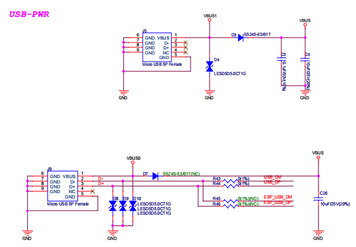
ESP32-C3-Lyra - Dedicated USB Power Supply Socket
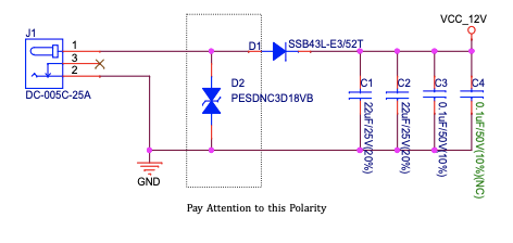
ESP32-C3-Lyra - Power Supply from 12 V DC Input
LED Strip Power Selection Switch
According to the working voltage and current of your LED strip, select a proper power adapter and the port, and toggle the LED Strip Power Selection Switch to the corresponding side to power up the LED strip.
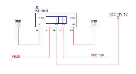
LED Strip Power Selection Switch
12 V to 5 V Buck Power
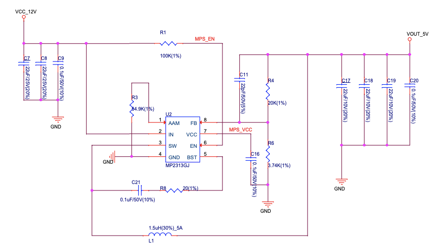
12 V to 5 V Buck Power Circuit
System 3.3 V Power
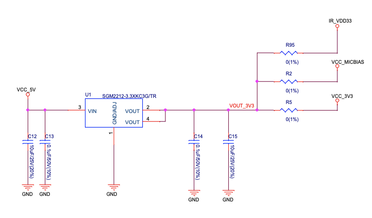
System 3.3 V Power Circuit
Connector
RGB LED Strip Connector (JP1)
No. |
Signal Name |
ESP32-C3 Pin |
|---|---|---|
1 |
VCC_12V_5V |
– |
2 |
LED_G |
GPIO6 |
3 |
LED_R |
GPIO5 |
4 |
LED_B |
GPIO4 |
Addressable LED Strip Connector (JP2)
No. |
Signal Name |
ESP32-C3 Pin |
|---|---|---|
1 |
VCC_12V_5V |
– |
2 |
DIN |
GPIO7 |
3 |
DIN |
GPIO7 |
4 |
GND |
– |
Pinout of Extension Headers
There are several pin headers available to connect external components, check the state of particular signal bus, or debug operation of ESP32-C3. Note that some signals are shared. See Section GPIO Allocation for details.
UART Header (JP12)
No. |
Signal Name |
ESP32-C3 Pin |
|---|---|---|
1 |
VCC_3V3 |
– |
2 |
ESP_EN |
EN |
3 |
ESP_BOOT |
GPIO9 |
4 |
ESP_UART_RXD |
U0RXD |
5 |
ESP_UART_TXD |
U0TXD |
6 |
GND |
– |
I2C Header (JP8)
No. |
Signal Name |
ESP32-C3 Pin |
|---|---|---|
1 |
VCC_3V3 |
– |
2 |
I2C_CLK |
GPIO8 |
3 |
I2C_DATA |
GPIO9 |
4 |
GND |
– |
Hardware Revision Details
No previous revisions.
Ordering
If you order a few samples, each board comes in an individual package.
For retail orders, please go to the official website https://www.espressif.com/en/company/contact/buy-a-sample, or directly order in our Taobao shop https://world.taobao.com/item/677273363812.htm?spm=a21wu.12321156-tw.recommend-tpp.4.19a61924ZMaqpf.
For wholesale orders, please go to the official website https://www.espressif.com/en/contact-us/sales-questions.