ESP32-LyraTD-MSC V2.2 Getting Started Guide
This guide provides users with functional descriptions, configuration options for ESP32-LyraTD-MSC V2.2 audio development board, as well as how to get started with the ESP32-LyraTD-MSC board.
The ESP32-LyraTD-MSC is a hardware platform designed for smart speakers and AI applications. It supports Acoustic Echo Cancellation (AEC), Automatic Speech Recognition (ASR), Wake-up Interrupt and Voice Interaction.
What You Need
2 x Speaker or headphones with a 3.5 mm jack. If you use a speaker, it is recommended to choose one no more than 3 watts, and JST PH 2.0 2-Pin plugs are needed. In case you do not have this type of plug it is also fine to use Dupont female jumper wires during development.
2 x Micro-USB 2.0 cables, Type A to Micro B
1 × PC loaded with Windows, Linux or Mac OS
If you like to start using this board right now, go directly to section Start Application Development.
Overview
The ESP32-LyraTD-MSC V2.2 is an audio development board produced by Espressif built around ESP32. It is intended for smart speakers and AI applications, by providing hardware for digital signal processing, microphone array and additional RAM on top of what is already onboard of the ESP32 chip.
This audio development board consists of two parts: the upper board (B), which provides a three-microphone array, function keys and LED lights; and the lower board (A), which integrates ESP32-WROVER-E, a MicroSemi Digital Signal Processing (DSP) chip, and a power management module.
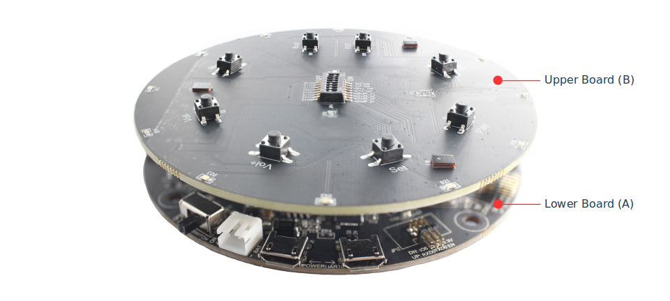
ESP32-LyraTD-MSC Side View
The specific hardware includes:
ESP32-WROVER-E Module
DSP (Digital Signal Processing) chip
Three digital Microphones that support far-field voice pick-up
2 x 3-watt Speaker output
Headphone output
MicroSD Card slot (1 line or 4 lines)
Individually controlled Twelve LEDs distributed in a circle on the board’s edge
Six Function Buttons that may be assigned user functions
Several interface ports: I2S, I2C, SPI and JTAG
Integrated USB-UART Bridge Chip
Li-ion Battery-Charge Management
The block diagram below presents main components of the ESP32-LyraTD-MSC and interconnections between components.

ESP32-LyraTD-MSC Block Diagram
Components
The following list and figure describe key components, interfaces and controls of the ESP32-LyraTD-MSC used in this guide. This covers just what is needed now. For additional details please refer to schematics provided in Related Documents.
- ESP32-WROVER-E Module
The ESP32-WROVER-E module contains ESP32 chip to provide Wi-Fi / Bluetooth connectivity and data processing power as well as integrates 4 MB external SPI flash and an additional 8 MB PSRAM for flexible data storage.
- DSP Chip
The Digital Signal Processing chip ZL38063 is used for Automatic Speech Recognition (ASR) applications. It captures audio data from an external microphone array and outputs audio signals through its Digital-to-Analog-Converter (DAC) port.
- Headphone Output
Output socket to connect headphones with a 3.5 mm stereo jack.
Note
The socket may be used with mobile phone headsets and is compatible with OMPT standard headsets only. It does not work with CTIA headsets. Please refer to Phone connector (audio) on Wikipedia.
- Left Speaker Output
Output socket to connect a speaker. The 4-ohm and 3-watt speaker is recommended. The pins have a 2.00 mm / 0.08” pitch.
- Right Speaker Output
Output socket to connect a speaker. The 4-ohm and 3-watt speaker is recommended. The pins have a 2.00 mm / 0.08” pitch.
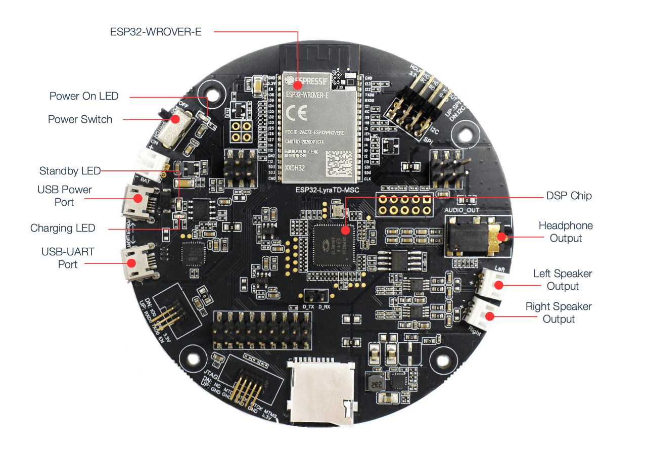
ESP32-LyraTD-MSC V2.2 Lower Board (A) Components
- USB-UART Port
Functions as the communication interface between a PC and the ESP32-WROVER-E module.
- USB Power Port
Provides the power supply for the board.
- Standby / Charging LEDs
The Standby green LED indicates that power has been applied to the Micro USB Port. The Charging red LED indicates that a battery connected to the Battery Socket is being charged.
- Power Switch
Power on/off knob: toggling it right powers the board on; otherwise powers the board off.
- Power On LED
Red LED indicating that Power Switch is turned on.
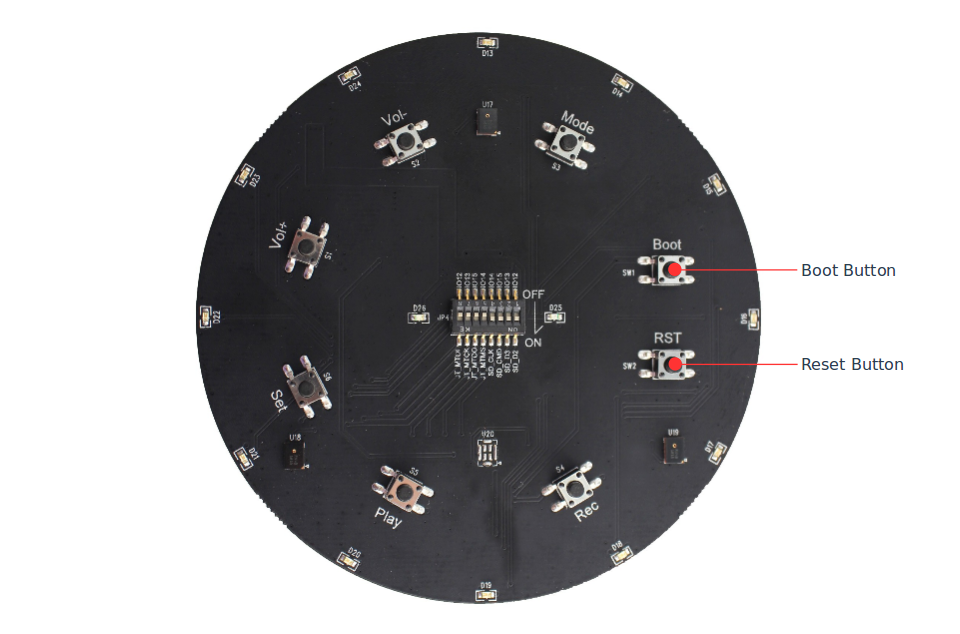
ESP32-LyraTD-MSC V2.2 Upper Board (B) Components
- Boot/Reset Buttons
Boot: holding down the Boot button and momentarily pressing the Reset button initiates the firmware upload mode. Then user can upload firmware through the serial port.
Reset: pressing this button alone resets the system.
Start Application Development
Before powering up the ESP32-LyraTD-MSC, please make sure that the board has been received in good condition with no obvious signs of damage. Both the lower A and the upper B board of the ESP32-LyraTD-MSC should be firmly connected together.
Initial Setup
Prepare the board for loading of the first sample application:
Connect speakers to the Right and Left Speaker Output. Connecting headphones to the Headphone Output is an option.
Plug in the Micro-USB cables to the PC and to both USB ports of the ESP32-LyraTD-MSC.
The Standby LED (green) should turn on. Assuming that a battery is not connected, the Charging LED (red) will blink every couple of seconds.
Toggle right the Power Switch.
The red Power On LED should turn on.
If this is what you see on the LEDs, the board should be ready for application upload. Now prepare the PC by loading and configuring development tools what is discussed in the next section.
Develop Applications
Once the board is initially set up and checked, you can start preparing the development tools. The Section Installation Step by Step will walk you through the following steps:
Set up ESP-IDF to get a common development framework for the ESP32 (and ESP32-S2) chips in C language;
Get ESP-ADF to install the API specific to audio applications;
Setup Path to ESP-ADF to make the framework aware of the audio specific API;
Start a Project that will provide a sample audio application for the board;
Connect Your Device to prepare the application for loading;
Build the Project to finally run the application and play some music.
Revision History
Changed the integrated module to ESP32-WROVER-E from ESP32-WROVER-B.