I2C
About
I2C (Inter-Integrated Circuit) / TWI (Two-wire Interface) is a widely used serial communication to connect devices in a short distance. This is one of the most common peripherals used to connect sensors, EEPROMs, RTC, ADC, DAC, displays, OLED, and many other devices and microcontrollers.
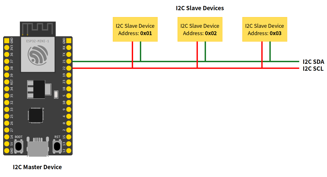
This serial communication is considered as a low-speed bus, and multiple devices can be connected on the same two-wires bus, each with a unique 7-bits address (up to 128 devices). These two wires are called SDA (serial data line) and SCL (serial clock line).
Note
The SDA and SCL lines require pull-up resistors. See the device datasheet for more details about the resistors’ values and the operating voltage.
I2C Modes
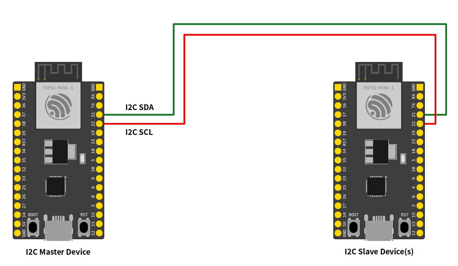
The I2C can be used in two different modes:
- I2C Master Mode
In this mode, the ESP32 generates the clock signal and initiates the communication with the slave device.
- I2C Slave Mode
The slave mode, the clock is generated by the master device and responds to the master if the destination address is the same as the destination.
Arduino-ESP32 I2C API
The ESP32 I2C library is based on the Arduino Wire Library and implements a few more APIs, described in this documentation.
I2C Common API
Here are the common functions used for master and slave modes.
begin
This function is used to start the peripheral using the default configuration.
bool begin();
This function will return true if the peripheral was initialized correctly.
setPins
This function is used to define the SDA and SCL pins.
Note
Call this function before begin to change the pins from the default ones.
bool setPins(int sdaPin, int sclPin);
sdaPinsets the GPIO to be used as the I2C peripheral data line.sclPinsets the GPIO to be used as the I2C peripheral clock line.
The default pins may vary from board to board. On the Generic ESP32 the default I2C pins are:
sdaPinGPIO21sclPinGPIO22
This function will return true if the peripheral was configured correctly.
setClock
Use this function to set the bus clock. The default value will be used if this function is not used.
bool setClock(uint32_t frequency);
frequencysets the bus frequency clock.
This function will return true if the clock was configured correctly.
getClock
Use this function to get the bus clock.
uint32_t getClock();
This function will return the current frequency configuration.
setTimeOut
Set the bus timeout given in milliseconds. The default value is 50ms.
void setTimeOut(uint16_t timeOutMillis);
timeOutMillissets the timeout in ms.
getTimeOut
Get the bus timeout in milliseconds.
uint16_t getTimeOut();
This function will return the current timeout configuration.
write
This function writes data to the buffer.
size_t write(uint8_t);
or
size_t write(const uint8_t *, size_t);
The return will be the size of the data added to the buffer.
end
This function will finish the communication and release all the allocated resources. After calling end you need to use begin again in order to initialize the I2C driver again.
bool end();
I2C Master Mode
This mode is used to initiate communication to the slave.
Basic Usage
To start using I2C master mode on the Arduino, the first step is to include the Wire.h header to the sketch.
#include "Wire.h"
Now, we can start the peripheral configuration by calling begin function.
Wire.begin();
By using begin without any arguments, all the settings will be done by using the default values. To set the values by your own, see the function description. This function is described here: i2c begin
After calling begin, we can start the transmission by calling beginTransmission and passing the I2C slave address:
Wire.beginTransmission(I2C_DEV_ADDR);
To write some bytes to the slave, use the write function.
Wire.write(x);
You can pass different data types using write function. This function is described here: i2c write
Note
The write function does not write directly to the slave device but adds to the I2C buffer. To do so, you need to use the endTransmission function to send the buffered bytes to the slave device.
Wire.endTransmission(true);
After calling endTransmission, the data stored in the I2C buffer will be transmitted to the slave device.
Now you can request a reading from the slave device. The requestFrom will ask for a readout to the selected device by giving the address and the size.
Wire.requestFrom(I2C_DEV_ADDR, SIZE);
and the readBytes will read it.
Wire.readBytes(temp, error);
I2C Master APIs
Here are the I2C master APIs. These function are intended to be used only for master mode.
begin
In master mode, the begin function can be used by passing the pins and bus frequency. Use this function only for the master mode.
bool begin(int sdaPin, int sclPin, uint32_t frequency)
Alternatively, you can use the begin function without any argument to use all default values.
This function will return true if the peripheral was initialized correctly.
beginTransmission
This function is used to star a communication process with the slave device. Call this function by passing the slave address before writing the message to the buffer.
void beginTransmission(uint16_t address)
endTransmission
After writing to the buffer using i2c write, use the function endTransmission to send the message to the slave device address defined on the beginTransmission function.
uint8_t endTransmission(bool sendStop);
sendStopenables (true) or disables (false) the stop signal (only used in master mode).
Calling the this function without sendStop is equivalent to sendStop = true.
uint8_t endTransmission(void);
This function will return the error code.
requestFrom
To read from the slave device, use the requestFrom function.
uint8_t requestFrom(uint16_t address, uint8_t size, bool sendStop)
addressset the device address.sizedefine the size to be requested.sendStopenables (true) or disables (false) the stop signal.
This function will return the number of bytes read from the device.
Example Application - WireMaster.ino
Here is an example of how to use the I2C in Master Mode.
#include "Wire.h"

#define I2C_DEV_ADDR 0x55

uint32_t i = 0;

void setup() {
  Serial.begin(115200);
  Serial.setDebugOutput(true);
  Wire.begin();
}

void loop() {
  delay(5000);

  //Write message to the slave
  Wire.beginTransmission(I2C_DEV_ADDR);
  Wire.printf("Hello World! %lu", i++);
  uint8_t error = Wire.endTransmission(true);
  Serial.printf("endTransmission: %u\n", error);

  //Read 16 bytes from the slave
  uint8_t bytesReceived = Wire.requestFrom(I2C_DEV_ADDR, 16);
  Serial.printf("requestFrom: %u\n", bytesReceived);
  if((bool)bytesReceived){ //If received more than zero bytes
    uint8_t temp[bytesReceived];
    Wire.readBytes(temp, bytesReceived);
    log_print_buf(temp, bytesReceived);
  }
}
I2C Slave Mode
This mode is used to accept communication from the master.
Basic Usage
To start using I2C as slave mode on the Arduino, the first step is to include the Wire.h header to the scketch.
#include "Wire.h"
Before calling begin we must create two callback functions to handle the communication with the master device.
Wire.onReceive(onReceive);
and
Wire.onRequest(onRequest);
The onReceive will handle the request from the master device uppon a slave read request and the onRequest will handle the answer to the master.
Now, we can start the peripheral configuration by calling begin function with the device address.
Wire.begin((uint8_t)I2C_DEV_ADDR);
By using begin without any arguments, all the settings will be done by using the default values. To set the values by your own, see the function description. This function is described here: i2c begin
For ESP32 only!
Use the function slaveWrite in order to pre-write to the slave response buffer. This is used only for the ESP32 in order to add the slave capability on the chip and keep compatability with Arduino.
Wire.slaveWrite((uint8_t *)message, strlen(message));
I2C Slave APIs
Here are the I2C slave APIs. These function are intended to be used only for slave mode.
begin
In slave mode, the begin function must be used by passing the slave address. You can also define the pins and the bus frequency.
bool Wire.begin(uint8_t addr, int sdaPin, int sclPin, uint32_t frequency)
This function will return true if the peripheral was initialized correctly.
onReceive
The onReceive function is used to define the callback for the data received from the master.
void onReceive( void (*)(int) );
onRequest
The onRequest function is used to define the callback for the data to be send to the master.
void onRequest( void (*)(void) );
slaveWrite
The slaveWrite function writes on the slave response buffer before receiving the response message. This function is only used for adding the slave compatability for the ESP32.
Warning
This function is only required for the ESP32. You don’t need to use for ESP32-S2 and ESP32-C3.
size_t slaveWrite(const uint8_t *, size_t);
Example Application - WireSlave.ino
Here is an example of how to use the I2C in Slave Mode.
#include "Wire.h"

#define I2C_DEV_ADDR 0x55

uint32_t i = 0;

void onRequest(){
  Wire.print(i++);
  Wire.print(" Packets.");
  Serial.println("onRequest");
}

void onReceive(int len){
  Serial.printf("onReceive[%d]: ", len);
  while(Wire.available()){
    Serial.write(Wire.read());
  }
  Serial.println();
}

void setup() {
  Serial.begin(115200);
  Serial.setDebugOutput(true);
  Wire.onReceive(onReceive);
  Wire.onRequest(onRequest);
  Wire.begin((uint8_t)I2C_DEV_ADDR);

#if CONFIG_IDF_TARGET_ESP32
  char message[64];
  snprintf(message, 64, "%lu Packets.", i++);
  Wire.slaveWrite((uint8_t *)message, strlen(message));
#endif
}

void loop() {

}