Controller Area Network (CAN)
Overview
The ESP32’s peripherals contains a CAN Controller that supports Standard Frame Format (11-bit ID) and Extended Frame Format (29-bit ID) of the CAN2.0B specification.
Warning
The ESP32 CAN controller is not compatible with CAN FD frames and will interpret such frames as errors.
This programming guide is split into the following sections:
Basic CAN Concepts
Note
The following section only covers the basic aspects of CAN. For full details, see the CAN2.0B specification
The CAN protocol is a multi-master, multi-cast communication protocol with error detection/signalling and inbuilt message prioritization. The CAN protocol is commonly used as a communication bus in automotive applications.
Multi-master: Any node in a CAN bus is allowed initiate the transfer of data.
Multi-cast: When a node transmits a message, all nodes are able to receive the message (broadcast). However some nodes can selective choose which messages to accept via the use of acceptance filtering (multi-cast).
Error Detection and Signalling: Every CAN node will constantly monitor the CAN bus. When any node detects an error, it will signal the error by transmitting an error frame. Other nodes will receive the error frame and transmit their own error frames in response. This will result in an error detection being propagated to all nodes on the bus.
Message Priorities: If two nodes attempt to transmit simultaneously, the node transmitting the message with the lower ID will win arbitration. All other nodes will become receivers ensuring there is at most one transmitter at any time.
CAN Message Frames
The CAN2.0B specification contains two frame formats known as Extended Frame and Standard Frame which contain 29-bit IDs and 11-bit IDs respectively. A CAN message consists of the following components
- 29-bit or 11-bit ID
- Data Length Code (DLC) between 0 to 8
- Up to 8 bytes of data (should match DLC)
Error States and Counters
The CAN2.0B specification implements fault confinement by requiring every CAN node to maintain two internal error counters known as the Transmit Error Counter (TEC) and the Receive Error Counter (REC). The two error counters are used to determine a CAN node’s error state, and the counters are incremented and decremented following a set of rules (see CAN2.0B specification). These error states are known as Error Active, Error Passive, and Bus-Off.
Error Active: A CAN node is Error Active when both TEC and REC are less than 128 and indicates a CAN node is operating normally. Error Active nodes are allowed to participate in CAN bus activities, and will actively signal any error conditions it detects by transmitting an Active Error Flag over the CAN bus.
Error Passive: A CAN node is Error Passive when either the TEC or REC becomes greater than or equal to 128. Error Passive nodes are still able to take part in CAN bus activities, but will instead transmit a Passive Error Flag upon detection of an error.
Bus-Off: A CAN node becomes Bus-Off when the TEC becomes greater than or equal to 256. A Bus-Off node is unable take part in CAN bus activity and will remain so until it undergoes bus recovery.
Signals Lines and Transceiver
The CAN controller does not contain a internal transceiver and therefore requires an external transceiver to operate. The type of external transceiver will depend on the application’s physical layer specification (e.g. using SN65HVD23X transceivers for ISO 11898-2 compatibility).
The CAN controller’s interface consists of 4 signal lines known as TX, RX, BUS-OFF, and CLKOUT. These four signal lines can be routed through the GPIO Matrix to GPIOs.
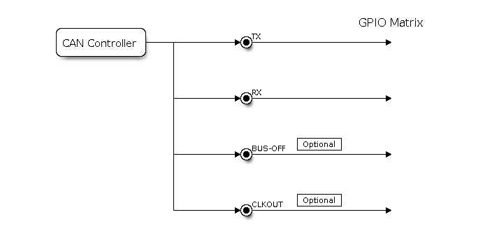
Signal lines of the CAN controller
TX and RX: The TX and RX signal lines are required to interface with an external CAN transceiver. Both signal lines represent/interpret a dominant bit as a low logic level (0V), and a recessive bit as a high logic level (3.3V).
BUS-OFF: The BUS-OFF signal line is optional and is set to a low logic level (0V) whenever the CAN controller reaches a bus-off state. The BUS-OFF signal line is set to a high logic level (3.3V) otherwise.
CLKOUT: The CLKOUT signal line is optional and outputs a prescaled version of the CAN controller’s source clock (APB Clock).
Note
An external transceiver must internally tie the TX input and the RX output such that a change in logic level to the TX signal line can be observed on the RX line. Failing to do so will cause the CAN controller to interpret differences in logic levels between the two signal lines as a lost in arbitration or a bit error.
Configuration
Operating Modes
The CAN driver supports the following modes of operations:
Normal Mode: The normal operating mode allows the CAN controller to take part in bus activities such as transmitting and receiving messages/error frames. Acknowledgement from another CAN node is required when transmitting message frames.
No Ack Mode: The No Acknowledgement mode is similar to normal mode, however acknowledgements are not required when transmitting message frames. This mode is useful when self testing the CAN controller.
Listen Only Mode: This mode will prevent the CAN controller from taking part in bus activities. Therefore transmissions of messages/acknowledgement/error frames will be disabled. However the the CAN controller will still be able to receive messages (without acknowledging). This mode is suited for applications such as CAN bus monitoring.
Alerts
The CAN driver contains an alert feature which is used to notify the application level of certain CAN driver events. Alerts are selectively enabled when the CAN driver is installed, but can be reconfigured during runtime by calling can_reconfigure_alerts(). The application can then wait for any enabled alerts to occur by calling can_read_alerts(). The CAN driver supports the following alerts:
| Alert | Description |
|---|---|
CAN_ALERT_TX_IDLE |
No more messages queued for transmission |
CAN_ALERT_TX_SUCCESS |
The previous transmission was successful |
CAN_ALERT_BELOW_ERR_WARN |
Both error counters have dropped below error warning limit |
CAN_ALERT_ERR_ACTIVE |
CAN controller has become error active |
CAN_ALERT_RECOVERY_IN_PROGRESS |
CAN controller is undergoing bus recovery |
CAN_ALERT_BUS_RECOVERED |
CAN controller has successfully completed bus recovery |
CAN_ALERT_ARB_LOST |
The previous transmission lost arbitration |
CAN_ALERT_ABOVE_ERR_WARN |
One of the error counters have exceeded the error warning limit |
CAN_ALERT_BUS_ERROR |
A (Bit, Stuff, CRC, Form, ACK) error has occurred on the bus |
CAN_ALERT_TX_FAILED |
The previous transmission has failed |
CAN_ALERT_RX_QUEUE_FULL |
The RX queue is full causing a received frame to be lost |
CAN_ALERT_ERR_PASS |
CAN controller has become error passive |
CAN_ALERT_BUS_OFF |
Bus-off condition occurred. CAN controller can no longer influence bus |
Note
The error warning limit can be used to preemptively warn the application of bus errors before the error passive state is reached. By default the CAN driver sets the error warning limit to 96. The CAN_ALERT_ABOVE_ERR_WARN is raised when the TEC or REC becomes larger then or equal to the error warning limit. The CAN_ALERT_BELOW_ERR_WARN is raised when both TEC and REC return back to values below 96.
Note
When enabling alerts, the CAN_ALERT_AND_LOG flag can be used to cause the CAN driver to log any raised alerts to UART. The CAN_ALERT_ALL and CAN_ALERT_NONE macros can also be used to enable/disable all alerts during configuration/reconfiguration.
Bit Timing
The operating bit rate of the CAN controller is configured using the can_timing_config_t structure. The period of each bit is made up of multiple time quanta, and the period of a time quanta is determined by a prescaled version of the CAN controller’s source clock. A single bit contains the following segments in the following order:
- The Synchronization Segment consists of a single time quanta
- Timing Segment 1 consists of 1 to 16 time quanta before sample point
- Timing Segment 2 consists of 1 to 8 time quanta after sample point
The Baudrate Prescaler is used to determine the period of each time quanta by dividing the CAN controller’s source clock (80 MHz APB clock). The brp can be any even number from 2 to 128. If the ESP32 is a revision 2 or later chip, the brp will also support any multiple of 4 from 132 to 256, and can be enabled by setting the CONFIG_ESP32_REV_MIN to revision 2 or higher.
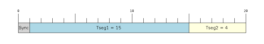
Bit timing configuration for 500kbit/s given BRP = 8
The sample point of a bit is located on the intersection of Timing Segment 1 and 2. Enabling Triple Sampling will cause 3 time quanta to be sampled per bit instead of 1 (extra samples are located at the tail end of Timing Segment 1).
The Synchronization Jump Width is used to determined the maximum number of time quanta a single bit time can be lengthened/shortened for synchronization purposes. sjw can range from 1 to 4.
Note
Multiple combinations of brp, tseg_1, tseg_2, and sjw can achieve the same bit rate. Users should tune these values to the physical characteristics of their CAN bus by taking into account factors such as propagation delay, node information processing time, and phase errors.
Bit timing macro initializers are also available for commonly used CAN bus bit rates. The following macro initializers are provided by the CAN driver.
CAN_TIMING_CONFIG_12_5KBITS()CAN_TIMING_CONFIG_16KBITS()CAN_TIMING_CONFIG_20KBITS()CAN_TIMING_CONFIG_25KBITS()CAN_TIMING_CONFIG_50KBITS()CAN_TIMING_CONFIG_100KBITS()CAN_TIMING_CONFIG_125KBITS()CAN_TIMING_CONFIG_250KBITS()CAN_TIMING_CONFIG_500KBITS()CAN_TIMING_CONFIG_800KBITS()CAN_TIMING_CONFIG_1MBITS()
Note
The macro initializers for 12.5K, 16K, and 20K bit rates are only available for ESP32 revision 2 or later.
Acceptance Filter
The CAN controller contains a hardware acceptance filter which can be used to filter CAN messages of a particular ID. A node that filters out a message will not receive the message, but will still acknowledge it. Acceptances filters can make a node more efficient by filtering out messages sent over the CAN bus that are irrelevant to the CAN node in question. The CAN controller’s acceptance filter is configured using two 32-bit values within can_filter_config_t known as the acceptance code and the acceptance mask.
The acceptance code specifies the bit sequence which a message’s ID, RTR, and data bytes must match in order for the message to be received by the CAN controller. The acceptance mask is a bit sequence specifying which bits of the acceptance code can be ignored. This allows for a messages of different IDs to be accepted by a single acceptance code.
The acceptance filter can be used under Single or Dual Filter Mode. Single Filter Mode will use the acceptance code and mask to define a single filter. This allows for the first two data bytes of a standard frame to be filtered, or the entirety of an extended frame’s 29-bit ID. The following diagram illustrates how the 32-bit acceptance code and mask will be interpreted under Single Filter Mode (Note: The yellow and blue fields represent standard and extended CAN frames respectively).
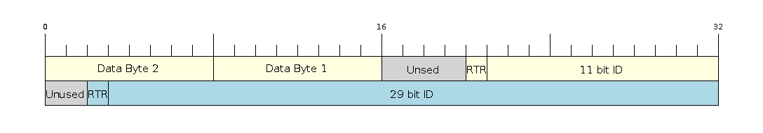
Bit layout of single filter mode (Right side MSBit)
Dual Filter Mode will use the acceptance code and mask to define two separate filters allowing for increased flexibility of ID’s to accept, but does not allow for all 29-bits of an extended ID to be filtered. The following diagram illustrates how the 32-bit acceptance code and mask will be interpreted under Dual Filter Mode (Note: The yellow and blue fields represent standard and extended CAN frames respectively).
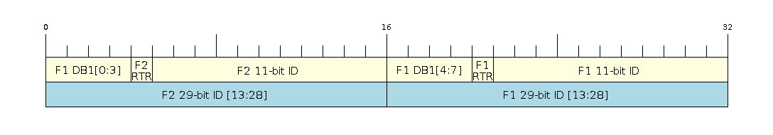
Bit layout of dual filter mode (Right side MSBit)
Disabling TX Queue
The TX queue can be disabled during configuration by setting the tx_queue_len member of can_general_config_t to 0. This will allow applications that do not require message transmission to save a small amount of memory when using the CAN driver.
Driver Operation
The CAN driver is designed with distinct states and strict rules regarding the functions or conditions that trigger a state transition. The following diagram illustrates the various states and their transitions.
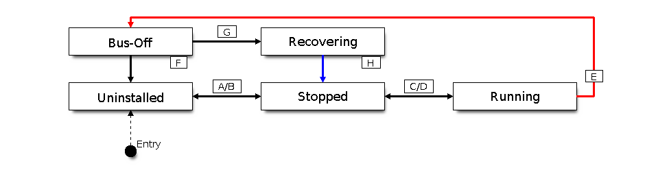
State transition diagram of the CAN driver (see table below)
| Label | Transition | Action/Condition |
|---|---|---|
| A | Uninstalled -> Stopped | can_driver_install() |
| B | Stopped -> Uninstalled | can_driver_uninstall() |
| C | Stopped -> Running | can_start() |
| D | Running -> Stopped | can_stop() |
| E | Running -> Bus-Off | Transmit Error Counter >= 256 |
| F | Bus-Off -> Uninstalled | can_driver_uninstall() |
| G | Bus-Off -> Recovering | can_initiate_recovery() |
| H | Recovering -> Stopped | 128 occurrences of bus-free signal |
Driver States
Uninstalled: In the uninstalled state, no memory is allocated for the driver and the CAN controller is powered OFF.
Stopped: In this state, the CAN controller is powered ON and the CAN driver has been installed. However the CAN controller will be unable to take part in any CAN bus activities such as transmitting, receiving, or acknowledging messages.
Running: In the running state, the CAN controller is able to take part in bus activities. Therefore messages can be transmitted/received/acknowledged. Furthermore the CAN controller will be able to transmit error frames upon detection of errors on the CAN bus.
Bus-Off: The bus-off state is automatically entered when the CAN controller’s Transmit Error Counter becomes greater than or equal to 256 (see CAN2.0B specification regarding error counter rules). The bus-off state indicates the occurrence of severe errors on the CAN bus or in the CAN controller. Whilst in the bus-off state, the CAN controller will be unable to take part in any CAN bus activities. To exit the bus-off state, the CAN controller must undergo the bus recovery process.
Recovering: The recovering state is entered when the CAN driver undergoes bus recovery. The CAN driver/controller will remain in the recovering state until the 128 occurrences of the bus-free signal (see CAN2.0B specification) is observed on the CAN bus.
Message Flags
The CAN driver distinguishes different types of CAN messages by using the various bit field members of the can_message_t structure. These bit field members help distinguish whether a message is in standard or extended format, an RTR, and the type of transmission to use when transmitting such a message. These bit field members can also be toggled using the the flags member of can_message_t and the following message flags:
| Flag | Description |
|---|---|
CAN_MSG_FLAG_EXTD |
Message is in Extended Frame Format (29bit ID) |
CAN_MSG_FLAG_RTR |
Message is a Remote Transmit Request |
CAN_MSG_FLAG_SS |
Transmit message using Single Shot Transmission (Message will not be retransmitted upon error or loss of arbitration). Unused for received message. |
CAN_MSG_FLAG_SELF |
Transmit message using Self Reception Request (Transmitted message will also received by the same node). Unused for received message. |
CAN_MSG_FLAG_DLC_NON_COMP |
Message’s Data length code is larger than 8. This will break compliance with CAN2.0B |
CAN_MSG_FLAG_NONE |
Clears all bit fields. Equivalent to a Standard Frame Format (11bit ID) Data Frame. |
Examples
Configuration & Installation
The following code snippet demonstrates how to configure, install, and start the CAN driver via the use of the various configuration structures, macro initializers, the can_driver_install() function, and the can_start() function.
#include "driver/gpio.h"
#include "driver/can.h"

void app_main()
{
    //Initialize configuration structures using macro initializers
    can_general_config_t g_config = CAN_GENERAL_CONFIG_DEFAULT(GPIO_NUM_21, GPIO_NUM_22, CAN_MODE_NORMAL);
    can_timing_config_t t_config = CAN_TIMING_CONFIG_500KBITS();
    can_filter_config_t f_config = CAN_FILTER_CONFIG_ACCEPT_ALL();

    //Install CAN driver
    if (can_driver_install(&g_config, &t_config, &f_config) == ESP_OK) {
        printf("Driver installed\n");
    } else {
        printf("Failed to install driver\n");
        return;
    }

    //Start CAN driver
    if (can_start() == ESP_OK) {
        printf("Driver started\n");
    } else {
        printf("Failed to start driver\n");
        return;
    }

    ...

}
The usage of macro initializers are not mandatory and each of the configuration structures can be manually.
Message Transmission
The following code snippet demonstrates how to transmit a message via the usage of the can_message_t type and can_transmit() function.
#include "driver/can.h"

...

//Configure message to transmit
can_message_t message;
message.identifier = 0xAAAA;
message.extd = 1;
message.data_length_code = 4;
for (int i = 0; i < 4; i++) {
    message.data[i] = 0;
}

//Queue message for transmission
if (can_transmit(&message, pdMS_TO_TICKS(1000)) == ESP_OK) {
    printf("Message queued for transmission\n");
} else {
    printf("Failed to queue message for transmission\n");
}
Message Reception
The following code snippet demonstrates how to receive a message via the usage of the can_message_t type and can_receive() function.
#include "driver/can.h"

...

//Wait for message to be received
can_message_t message;
if (can_receive(&message, pdMS_TO_TICKS(10000)) == ESP_OK) {
    printf("Message received\n");
} else {
    printf("Failed to receive message\n");
    return;
}

//Process received message
if (message.extd) {
    printf("Message is in Extended Format\n");
} else {
    printf("Message is in Standard Format\n");
}
printf("ID is %d\n", message.identifier);
if (!(message.rtr)) {
    for (int i = 0; i < message.data_length_code; i++) {
        printf("Data byte %d = %d\n", i, message.data[i]);
    }
}
Reconfiguring and Reading Alerts
The following code snippet demonstrates how to reconfigure and read CAN driver alerts via the use of the can_reconfigure_alerts() and can_read_alerts() functions.
#include "driver/can.h"

...

//Reconfigure alerts to detect Error Passive and Bus-Off error states
uint32_t alerts_to_enable = CAN_ALERT_ERR_PASS | CAN_ALERT_BUS_OFF;
if (can_reconfigure_alerts(alerts_to_enable, NULL) == ESP_OK) {
    printf("Alerts reconfigured\n");
} else {
    printf("Failed to reconfigure alerts");
}

//Block indefinitely until an alert occurs
uint32_t alerts_triggered;
can_read_alerts(&alerts_triggered, portMAX_DELAY);
Stop and Uninstall
The following code demonstrates how to stop and uninstall the CAN driver via the use of the can_stop() and can_driver_uninstall() functions.
#include "driver/can.h"

...

//Stop the CAN driver
if (can_stop() == ESP_OK) {
    printf("Driver stopped\n");
} else {
    printf("Failed to stop driver\n");
    return;
}

//Uninstall the CAN driver
if (can_driver_uninstall() == ESP_OK) {
    printf("Driver uninstalled\n");
} else {
    printf("Failed to uninstall driver\n");
    return;
}
Multiple ID Filter Configuration
The acceptance mask in can_filter_config_t can be configured such that two or more IDs will be accepted for a single filter. For a particular filter to accept multiple IDs, the conflicting bit positions amongst the IDs must be set in the acceptance mask. The acceptance code can be set to any one of the IDs.
The following example shows how the calculate the acceptance mask given multiple IDs:
ID1 =  11'b101 1010 0000
ID2 =  11'b101 1010 0001
ID3 =  11'b101 1010 0100
ID4 =  11'b101 1010 1000
//Acceptance Mask
MASK = 11'b000 0000 1101
Application Examples
Network Example: The CAN Network example demonstrates communication between two ESP32s using the CAN driver API. One CAN node acts as a network master initiate and ceasing the transfer of a data from another CAN node acting as a network slave. The example can be found via peripherals/can/can_network.
Alert and Recovery Example: This example demonstrates how to use the CAN driver’s alert and bus recovery API. The example purposely introduces errors on the CAN bus to put the CAN controller into the Bus-Off state. An alert is used to detect the Bus-Off state and trigger the bus recovery process. The example can be found via peripherals/can/can_alert_and_recovery.
Self Test Example: This example uses the No Acknowledge Mode and Self Reception Request to cause the CAN controller to send and simultaneously receive a series of messages. This example can be used to verify if the connections between the CAN controller and the external transceiver are working correctly. The example can be found via peripherals/can/can_self_test.
API Reference
Header File
Structures
-
struct
can_message_t¶ Structure to store a CAN message.
- Note
- Note
- The flags member is deprecated
Public Members
-
uint32_t
extd¶ Extended Frame Format (29bit ID)
-
uint32_t
rtr¶ Message is a Remote Transmit Request
-
uint32_t
ss¶ Transmit as a Single Shot Transmission. Unused for received.
-
uint32_t
self¶ Transmit as a Self Reception Request. Unused for received.
-
uint32_t
dlc_non_comp¶ Message’s Data length code is larger than 8. This will break compliance with CAN2.0B.
-
uint32_t
reserved¶ Reserved bits
-
uint32_t
flags¶ Alternate way to set message flags using message flag macros (see documentation)
-
uint32_t
identifier¶ 11 or 29 bit identifier
-
uint8_t
data_length_code¶ Data length code
-
uint8_t
data[CAN_FRAME_MAX_DLC]¶ Data bytes (not relevant in RTR frame)
-
struct
can_timing_config_t¶ Structure for bit timing configuration of the CAN driver.
- Note
- Macro initializers are available for this structure
Public Members
-
uint32_t
brp¶ Baudrate prescaler (i.e., APB clock divider) can be any even number from 2 to 128. For ESP32 Rev 2 or later, multiples of 4 from 132 to 256 are also supported
-
uint8_t
tseg_1¶ Timing segment 1 (Number of time quanta, between 1 to 16)
-
uint8_t
tseg_2¶ Timing segment 2 (Number of time quanta, 1 to 8)
-
uint8_t
sjw¶ Synchronization Jump Width (Max time quanta jump for synchronize from 1 to 4)
-
bool
triple_sampling¶ Enables triple sampling when the CAN controller samples a bit
-
struct
can_filter_config_t¶ Structure for acceptance filter configuration of the CAN driver (see documentation)
- Note
- Macro initializers are available for this structure
Macros
-
CAN_EXTD_ID_MASK¶ CAN2.0B Constants.
Bit mask for 29 bit Extended Frame Format ID
-
CAN_STD_ID_MASK¶ Bit mask for 11 bit Standard Frame Format ID
-
CAN_FRAME_MAX_DLC¶ Max data bytes allowed in CAN2.0
-
CAN_FRAME_EXTD_ID_LEN_BYTES¶ EFF ID requires 4 bytes (29bit)
-
CAN_FRAME_STD_ID_LEN_BYTES¶ SFF ID requires 2 bytes (11bit)
-
CAN_ERR_PASS_THRESH¶ Error counter threshold for error passive
Enumerations
-
enum
can_mode_t¶ CAN Controller operating modes.
Values:
-
CAN_MODE_NORMAL¶ Normal operating mode where CAN controller can send/receive/acknowledge messages
-
CAN_MODE_NO_ACK¶ Transmission does not require acknowledgment. Use this mode for self testing
-
CAN_MODE_LISTEN_ONLY¶ The CAN controller will not influence the bus (No transmissions or acknowledgments) but can receive messages
-
Header File
Functions
-
esp_err_t
can_driver_install(const can_general_config_t *g_config, const can_timing_config_t *t_config, const can_filter_config_t *f_config)¶ Install CAN driver.
This function installs the CAN driver using three configuration structures. The required memory is allocated and the CAN driver is placed in the stopped state after running this function.
- Note
- Macro initializers are available for the configuration structures (see documentation)
- Note
- To reinstall the CAN driver, call can_driver_uninstall() first
- Return
- ESP_OK: Successfully installed CAN driver
- ESP_ERR_INVALID_ARG: Arguments are invalid
- ESP_ERR_NO_MEM: Insufficient memory
- ESP_ERR_INVALID_STATE: Driver is already installed
- Parameters
g_config: General configuration structuret_config: Timing configuration structuref_config: Filter configuration structure
-
esp_err_t
can_driver_uninstall(void)¶ Uninstall the CAN driver.
This function uninstalls the CAN driver, freeing the memory utilized by the driver. This function can only be called when the driver is in the stopped state or the bus-off state.
- Warning
- The application must ensure that no tasks are blocked on TX/RX queues or alerts when this function is called.
- Return
- ESP_OK: Successfully uninstalled CAN driver
- ESP_ERR_INVALID_STATE: Driver is not in stopped/bus-off state, or is not installed
-
esp_err_t
can_start(void)¶ Start the CAN driver.
This function starts the CAN driver, putting the CAN driver into the running state. This allows the CAN driver to participate in CAN bus activities such as transmitting/receiving messages. The RX queue is reset in this function, clearing any unread messages. This function can only be called when the CAN driver is in the stopped state.
- Return
- ESP_OK: CAN driver is now running
- ESP_ERR_INVALID_STATE: Driver is not in stopped state, or is not installed
-
esp_err_t
can_stop(void)¶ Stop the CAN driver.
This function stops the CAN driver, preventing any further message from being transmitted or received until can_start() is called. Any messages in the TX queue are cleared. Any messages in the RX queue should be read by the application after this function is called. This function can only be called when the CAN driver is in the running state.
- Warning
- A message currently being transmitted/received on the CAN bus will be ceased immediately. This may lead to other CAN nodes interpreting the unfinished message as an error.
- Return
- ESP_OK: CAN driver is now Stopped
- ESP_ERR_INVALID_STATE: Driver is not in running state, or is not installed
-
esp_err_t
can_transmit(const can_message_t *message, TickType_t ticks_to_wait)¶ Transmit a CAN message.
This function queues a CAN message for transmission. Transmission will start immediately if no other messages are queued for transmission. If the TX queue is full, this function will block until more space becomes available or until it timesout. If the TX queue is disabled (TX queue length = 0 in configuration), this function will return immediately if another message is undergoing transmission. This function can only be called when the CAN driver is in the running state and cannot be called under Listen Only Mode.
- Note
- This function does not guarantee that the transmission is successful. The TX_SUCCESS/TX_FAILED alert can be enabled to alert the application upon the success/failure of a transmission.
- Note
- The TX_IDLE alert can be used to alert the application when no other messages are awaiting transmission.
- Return
- ESP_OK: Transmission successfully queued/initiated
- ESP_ERR_INVALID_ARG: Arguments are invalid
- ESP_ERR_TIMEOUT: Timed out waiting for space on TX queue
- ESP_FAIL: TX queue is disabled and another message is currently transmitting
- ESP_ERR_INVALID_STATE: CAN driver is not in running state, or is not installed
- ESP_ERR_NOT_SUPPORTED: Listen Only Mode does not support transmissions
- Parameters
message: Message to transmitticks_to_wait: Number of FreeRTOS ticks to block on the TX queue
-
esp_err_t
can_receive(can_message_t *message, TickType_t ticks_to_wait)¶ Receive a CAN message.
This function receives a message from the RX queue. The flags field of the message structure will indicate the type of message received. This function will block if there are no messages in the RX queue
- Warning
- The flags field of the received message should be checked to determine if the received message contains any data bytes.
- Return
- ESP_OK: Message successfully received from RX queue
- ESP_ERR_TIMEOUT: Timed out waiting for message
- ESP_ERR_INVALID_ARG: Arguments are invalid
- ESP_ERR_INVALID_STATE: CAN driver is not installed
- Parameters
message: Received messageticks_to_wait: Number of FreeRTOS ticks to block on RX queue
-
esp_err_t
can_read_alerts(uint32_t *alerts, TickType_t ticks_to_wait)¶ Read CAN driver alerts.
This function will read the alerts raised by the CAN driver. If no alert has been when this function is called, this function will block until an alert occurs or until it timeouts.
- Note
- Multiple alerts can be raised simultaneously. The application should check for all alerts that have been enabled.
- Return
- ESP_OK: Alerts read
- ESP_ERR_TIMEOUT: Timed out waiting for alerts
- ESP_ERR_INVALID_ARG: Arguments are invalid
- ESP_ERR_INVALID_STATE: CAN driver is not installed
- Parameters
alerts: Bit field of raised alerts (see documentation for alert flags)ticks_to_wait: Number of FreeRTOS ticks to block for alert
-
esp_err_t
can_reconfigure_alerts(uint32_t alerts_enabled, uint32_t *current_alerts)¶ Reconfigure which alerts are enabled.
This function reconfigures which alerts are enabled. If there are alerts which have not been read whilst reconfiguring, this function can read those alerts.
- Return
- ESP_OK: Alerts reconfigured
- ESP_ERR_INVALID_STATE: CAN driver is not installed
- Parameters
alerts_enabled: Bit field of alerts to enable (see documentation for alert flags)current_alerts: Bit field of currently raised alerts. Set to NULL if unused
-
esp_err_t
can_initiate_recovery(void)¶ Start the bus recovery process.
This function initiates the bus recovery process when the CAN driver is in the bus-off state. Once initiated, the CAN driver will enter the recovering state and wait for 128 occurrences of the bus-free signal on the CAN bus before returning to the stopped state. This function will reset the TX queue, clearing any messages pending transmission.
- Note
- The BUS_RECOVERED alert can be enabled to alert the application when the bus recovery process completes.
- Return
- ESP_OK: Bus recovery started
- ESP_ERR_INVALID_STATE: CAN driver is not in the bus-off state, or is not installed
-
esp_err_t
can_get_status_info(can_status_info_t *status_info)¶ Get current status information of the CAN driver.
- Return
- ESP_OK: Status information retrieved
- ESP_ERR_INVALID_ARG: Arguments are invalid
- ESP_ERR_INVALID_STATE: CAN driver is not installed
- Parameters
status_info: Status information
-
esp_err_t
can_clear_transmit_queue(void)¶ Clear the transmit queue.
This function will clear the transmit queue of all messages.
- Note
- The transmit queue is automatically cleared when can_stop() or can_initiate_recovery() is called.
- Return
- ESP_OK: Transmit queue cleared
- ESP_ERR_INVALID_STATE: CAN driver is not installed or TX queue is disabled
Structures
-
struct
can_general_config_t¶ Structure for general configuration of the CAN driver.
- Note
- Macro initializers are available for this structure
Public Members
-
can_mode_t
mode¶ Mode of CAN controller
-
gpio_num_t
tx_io¶ Transmit GPIO number
-
gpio_num_t
rx_io¶ Receive GPIO number
-
gpio_num_t
clkout_io¶ CLKOUT GPIO number (optional, set to -1 if unused)
-
gpio_num_t
bus_off_io¶ Bus off indicator GPIO number (optional, set to -1 if unused)
-
uint32_t
tx_queue_len¶ Number of messages TX queue can hold (set to 0 to disable TX Queue)
-
uint32_t
rx_queue_len¶ Number of messages RX queue can hold
-
uint32_t
alerts_enabled¶ Bit field of alerts to enable (see documentation)
-
uint32_t
clkout_divider¶ CLKOUT divider. Can be 1 or any even number from 2 to 14 (optional, set to 0 if unused)
-
struct
can_status_info_t¶ Structure to store status information of CAN driver.
Public Members
-
can_state_t
state¶ Current state of CAN controller (Stopped/Running/Bus-Off/Recovery)
-
uint32_t
msgs_to_tx¶ Number of messages queued for transmission or awaiting transmission completion
-
uint32_t
msgs_to_rx¶ Number of messages in RX queue waiting to be read
-
uint32_t
tx_error_counter¶ Current value of Transmit Error Counter
-
uint32_t
rx_error_counter¶ Current value of Receive Error Counter
-
uint32_t
tx_failed_count¶ Number of messages that failed transmissions
-
uint32_t
rx_missed_count¶ Number of messages that were lost due to a full RX queue
-
uint32_t
arb_lost_count¶ Number of instances arbitration was lost
-
uint32_t
bus_error_count¶ Number of instances a bus error has occurred
-
can_state_t
Enumerations
-
enum
can_state_t¶ CAN driver states.
Values:
-
CAN_STATE_STOPPED¶ Stopped state. The CAN controller will not participate in any CAN bus activities
-
CAN_STATE_RUNNING¶ Running state. The CAN controller can transmit and receive messages
-
CAN_STATE_BUS_OFF¶ Bus-off state. The CAN controller cannot participate in bus activities until it has recovered
-
CAN_STATE_RECOVERING¶ Recovering state. The CAN controller is undergoing bus recovery
-