ESP32-LyraT V4.2 Getting Started Guide
This guide provides users with functional descriptions, configuration options for ESP32-LyraT V4.2 audio development board, as well as how to get started with the ESP32-LyraT board.
The ESP32-LyraT development board is a hardware platform designed for the dual-core ESP32 audio applications, e.g., Wi-Fi or BT audio speakers, speech-based remote controllers, smart-home appliances with audio functionality(ies), etc.
If you like to start using this board right now, go directly to section Start Application Development.
What You Need
2 × Speaker or headphones with a 3.5 mm jack. If you use a speaker, it is recommended to choose one no more than 3 watts, and JST PH 2.0 2-Pin plugs are needed. In case you do not have this type of plug it is also fine to use Dupont female jumper wires during development.
2 x Micro-USB 2.0 cables, Type A to Micro B
1 × PC loaded with Windows, Linux or Mac OS
Overview
The ESP32-LyraT V4.2 is an audio development board produced by Espressif built around ESP32. It is intended for audio applications, by providing hardware for audio processing and additional RAM on top of what is already onboard of the ESP32 chip. The specific hardware includes:
ESP32-WROVER Module*
Audio Codec Chip
Dual Microphones on board
Headphone input
2 x 3-watt Speaker output
Dual Auxiliary Input
MicroSD Card slot (1 line or 4 lines)
Six buttons (2 physical buttons and 4 touch buttons)
JTAG header
Integrated USB-UART Bridge Chip
Li-ion Battery-Charge Management
The superscript * indicates that the product is in EOL status. The same applies below.
The block diagram below presents main components of the ESP32-LyraT and interconnections between components.
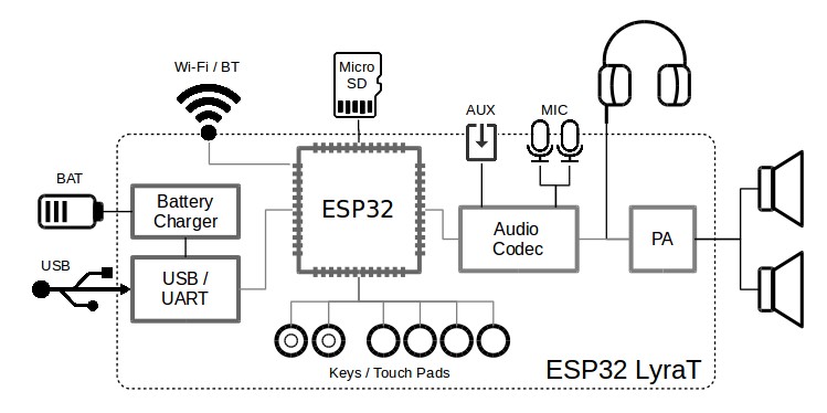
ESP32-LyraT Block Diagram
Functional Description
The following list and figure describe key components, interfaces and controls of the ESP32-LyraT board.
- ESP32-WROVER Module*
The ESP32-WROVER module* contains ESP32 chip to provide Wi-Fi / BT connectivity and data processing power as well as integrates 32 Mbit SPI flash and 32 Mbit PSRAM for flexible data storage.
- Green and Red LEDs
Two general purpose LEDs controlled by ESP32-WROVER Module* to indicate certain operation states of the audio application using dedicated API.
- Function DIP Switch
Used to configure function of GPIO12 to GPIO15 pins that are shared between devices, primarily between JTAG Header and MicroSD Card. By default, the MicroSD Card is enabled with all switches in OFF position. To enable the JTAG Header instead, switches in positions 3, 4, 5 and 6 should be put ON. If JTAG is not used and MicroSD Card is operated in the one-line mode, then GPIO12 and GPIO13 may be assigned to other functions. Please refer to ESP32 LyraT V4.2 schematic for more details.
- JTAG Header
Provides access to the JTAG interface of ESP32-WROVER Module*. It may be used for debugging, application upload, as well as implementing several other functions, e.g., Application Level Tracing. See JTAG Header / JP7 for pinout details. Before using JTAG signals to the header, Function DIP Switch should be enabled. Please note that when JTAG is in operation, MicroSD Card cannot be used and should be disconnected because some of JTAG signals are shared by both devices.
- UART Header
Serial port: provides access to the serial TX/RX signals between ESP32-WROVER Module* and USB-UART Bridge Chip.
- I2C Header
Provides access to the I2C interface. Both ESP32-WROVER Module* and Audio Codec Chip are connected to this interface. See I2C Header / JP5 for pinout details.
- MicroSD Card
The development board supports a MicroSD card in SPI/1-bit/4-bit modes, and can store or play audio files in the MicroSD card. See MicroSD Card / J5 for pinout details. Note that JTAG cannot be used and should be disconnected by setting Function DIP Switch when MicroSD Card is in operation, because some of signals are shared by both devices.
- I2S Header
Provides access to the I2S interface. Both ESP32-WROVER Module* and Audio Codec Chip are connected to this interface. See I2S Header / JP4 for pinout details.
- Left Microphone
Onboard microphone connected to IN1 of the Audio Codec Chip.
- AUX Input
Auxiliary input socket connected to IN2 (left and right channel) of the Audio Codec Chip. Use a 3.5 mm stereo jack to connect to this socket.
- Headphone Output
Output socket to connect headphones with a 3.5 mm stereo jack.
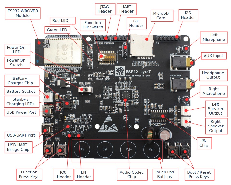
ESP32-LyraT V4.2 Board Layout
- Right Microphone
Onboard microphone connected to IN1 of the Audio Codec Chip.
- Left Speaker Output
Output socket to connect a speaker. The 4-ohm and 3-watt speaker is recommended. The pins have a 2.00 mm / 0.08” pitch.
- Right Speaker Output
Output socket to connect a speaker. The 4-ohm and 3-watt speaker is recommended. The pins have a 2.00 mm / 0.08” pitch.
- PA Chip
A power amplifier used to amplify stereo audio signal from the Audio Codec Chip for driving two speakers.
- Boot/Reset Press Keys
Boot: holding down the Boot button and momentarily pressing the Reset button initiates the firmware upload mode. Then user can upload firmware through the serial port. Reset: pressing this button alone resets the system.
- Touch Pad Buttons
Four touch pads labeled Play, Sel, Vol+ and Vol-. They are routed to ESP32-WROVER Module* and intended for development and testing of a UI for audio applications using dedicated API.
- Audio Codec Chip
The Audio Codec Chip, ES8388, is a low power stereo audio codec with a headphone amplifier. It consists of 2-channel ADC, 2-channel DAC, microphone amplifier, headphone amplifier, digital sound effects, analog mixing and gain functions. It is interfaced with ESP32-WROVER Module* over I2S and I2S buses to provide audio processing in hardware independently from the audio application.
- EN Header
Install a jumper on this header to enable automatic loading of application to the ESP32. Install or remove jumpers together on both IO0 and EN headers.
- IO0 Header
Install a jumper on this header to enable automatic loading of application to the ESP32. Install or remove jumpers together on both IO0 and EN headers.
- Function Press Keys
Two key labeled Rec and Mode. They are routed to ESP32-WROVER Module* and intended for developing and testing a UI for audio applications using dedicated API.
- USB-UART Bridge Chip
A single chip USB-UART bridge provides up to 1 Mbps transfers rate.
- USB-UART Port
Functions as the communication interface between a PC and the ESP32 module.
- USB Power Port
Provides the power supply for the board.
- Standby / Charging LEDs
The Standby green LED indicates that power has been applied to the Micro USB Port. The Charging red LED indicates that a battery connected to the Battery Socket is being charged.
- Battery Charger Chip
Constant current & constant voltage linear charger for single cell lithium-ion batteries AP5056. Used for charging of a battery connected to the Battery Socket over the Micro USB Port.
- Power On Switch
Power on/off knob: toggling it to the left powers the board on; toggling it to the right powers the board off.
- Battery Socket
Two pins socket to connect a single cell Li-ion battery.
- Power On LED
Red LED indicating that Power On Switch is turned on.
Note
The Power On Switch does not affect / disconnect the Li-ion battery charging.
Hardware Setup Options
There are a couple of options to change the hardware configuration of the ESP32-LyraT board. The options are selectable with the Function DIP Switch.
Enable MicroSD Card in 1-wire Mode
DIP SW |
Position |
|---|---|
1 |
OFF |
2 |
OFF |
3 |
OFF |
4 |
OFF |
5 |
OFF |
6 |
OFF |
7 |
OFF 1 |
8 |
n/a |
AUX Input detection may be enabled by toggling the DIP SW 7 ON
In this mode:
JTAG functionality is not available
Vol- touch button is available for use with the API
Enable MicroSD Card in 4-wire Mode
DIP SW |
Position |
|---|---|
1 |
ON |
2 |
ON |
3 |
OFF |
4 |
OFF |
5 |
OFF |
6 |
OFF |
7 |
OFF |
8 |
n/a |
In this mode:
JTAG functionality is not available
Vol- touch button is not available for use with the API
AUX Input detection from the API is not available
Enable JTAG
DIP SW |
Position |
|---|---|
1 |
OFF |
2 |
OFF |
3 |
ON |
4 |
ON |
5 |
ON |
6 |
ON |
7 |
ON |
8 |
n/a |
In this mode:
MicroSD Card functionality is not available, remove the card from the slot
Vol- touch button is not available for use with the API
AUX Input detection from the API is not available
Allocation of ESP32 Pins
Several pins / terminals of ESP32 modules are allocated to the on board hardware. Some of them, like GPIO0 or GPIO2, have multiple functions. Please refer to the tables below or ESP32 LyraT V4.2 schematic for specific details.
Red / Green LEDs
ESP32 Pin |
LED Color |
|
|---|---|---|
1 |
GPIO19 |
Red LED |
2 |
GPIO22 |
Green LED |
Touch Pads
ESP32 Pin |
Touch Pad Function |
|
|---|---|---|
1 |
GPIO33 |
Play |
2 |
GPIO32 |
Set |
3 |
GPIO13 |
Vol- 1 |
4 |
GPIO27 |
Vol+ |
Vol- function is not available if JTAG is used. It is also not available for the MicroSD Card configured to operate in 4-wire mode.
MicroSD Card / J5
ESP32 Pin |
MicroSD Signal |
|
|---|---|---|
1 |
MTDI / GPIO12 |
DATA2 |
2 |
MTCK / GPIO13 |
CD / DATA3 |
3 |
MTDO / GPIO15 |
CMD |
4 |
MTMS / GPIO14 |
CLK |
5 |
GPIO2 |
DATA0 |
6 |
GPIO4 |
DATA1 |
7 |
GPIO21 |
CD |
UART Header / JP2
Header Pin |
|
|---|---|
1 |
3.3V |
2 |
TX |
3 |
RX |
4 |
GND |
EN and IO0 Headers / JP23 and J24
ESP32 Pin |
Header Pin |
|
|---|---|---|
1 |
n/a |
EN_Auto |
2 |
EN |
EN |
ESP32 Pin |
Header Pin |
|
|---|---|---|
1 |
n/a |
IO0_Auto |
2 |
GPIO0 |
IO0 |
I2S Header / JP4
I2C Header Pin |
ESP32 Pin |
|
|---|---|---|
1 |
MCLK |
GPI0 |
2 |
SCLK |
GPIO5 |
1 |
LRCK |
GPIO25 |
2 |
DSDIN |
GPIO26 |
3 |
ASDOUT |
GPIO35 |
3 |
GND |
GND |
I2C Header / JP5
I2C Header Pin |
ESP32 Pin |
|
|---|---|---|
1 |
SCL |
GPIO23 |
2 |
SDA |
GPIO18 |
3 |
GND |
GND |
JTAG Header / JP7
ESP32 Pin |
JTAG Signal |
|
|---|---|---|
1 |
MTDO / GPIO15 |
TDO |
2 |
MTCK / GPIO13 |
TCK |
3 |
MTDI / GPIO12 |
TDI |
4 |
MTMS / GPIO14 |
TMS |
Function DIP Switch / JP8
Switch OFF |
Switch ON |
|
|---|---|---|
1 |
GPIO12 not allocated |
MicroSD Card 4-wire |
2 |
Touch Vol- enabled |
MicroSD Card 4-wire |
3 |
MicroSD Card |
JTAG |
4 |
MicroSD Card |
JTAG |
5 |
MicroSD Card |
JTAG |
6 |
MicroSD Card |
JTAG |
7 |
MicroSD Card 4-wire |
AUX IN detect 1 |
8 |
not used |
not used |
The AUX Input signal pin should not be be plugged in when the system powers up. Otherwise the ESP32 may not be able to boot correctly.
Start Application Development
Before powering up the ESP32-LyraT, please make sure that the board has been received in good condition with no obvious signs of damage.
Initial Setup
Prepare the board for loading of the first sample application:
Install jumpers on IO0 and EN headers to enable automatic application upload. If there are no jumpers then upload may be triggered using Boot / RST buttons.
Connect speakers to the Right and Left Speaker Output.Connecting headphones to the Headphone Output is an option.
Plug in the Micro-USB cables to the PC and to both USB ports of the ESP32 LyraT.
The Standby LED (green) should turn on. Assuming that a battery is not connected, the Charging LED will blink every couple of seconds.
Toggle left the Power On Switch.
The red Power On LED should turn on.
If this is what you see on the LEDs, the board should be ready for application upload. Now prepare the PC by loading and configuring development tools what is discussed in the next section.
Develop Applications
Once the board is initially set up and checked, you can start preparing the development tools. The Section Installation Step by Step will walk you through the following steps:
Set up ESP-IDF to get a common development framework for the ESP32 (and ESP32-S2) chips in C language;
Get ESP-ADF to install the API specific to audio applications;
Set up env to make the framework aware of the audio specific API;
Start a Project that will provide a sample audio application for the board;
Connect Your Device to prepare the application for loading;
Build the Project to finally run the application and play some music.