ESP32-Korvo-DU1906
This user guide provides information on ESP32-Korvo-DU1906.

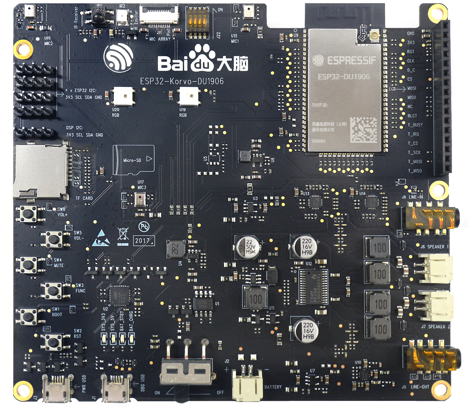
ESP32-Korvo-DU1906 (click to enlarge)
The document consists of the following major sections:
Getting Started: Provides an overview of the ESP32-Korvo-DU1906 and hardware/software setup instructions to get started.
Start Application Development: Provides more detailed information about the ESP32-Korvo-DU1906’s application development process.
Related Documents: Gives links to related documentaiton.
Getting Started
The core component of ESP32-Korvo-DU1906 includes an ESP32-DU1906 Bluetooth/Wi-Fi audio module, which is able to realize noise reduction, acoustic echo cancellation (AEC), beam formation and detection. ESP32-Korvo-DU1906 integrates power management, Bluetooth/Wi-Fi audio module, Coder-Decoder (CODEC), power amplifier, and etc., supports various functions such as:
ADC
Microphone array
SD card
Functional buttons
Indicator lights
Battery constant-current/constant-voltage linear power management chip
USB-to-UART conversion
LCD connector
What You Need
1 x PC loaded with Windows, Mac OS and Linux (Linux Operating System is recommended)
1 x ESP32-Korvo-DU1906
2 x Micro USB cables
2 x Speaker (4 Ohm, 2.5 W)
Overview
The biggest advantage of this development board is the audio chip – ESP32-DU1906, the core processing module, is an powerful AI module integrating Wi-Fi+Bluetooth+Bluetooth Low Energy RF and voice/speech signal processing functions, which can be used in various fields. By providing the leading end-to-end audio solutions, high-efficient integrated AI service capabilities, and an on-device AIOT platform which integrates ends and devices, this board is able to largely reduce the threshold for AI access.
DU1906 is a voice processing flagship chip launched by Baidu. This chip has a highly integrated algorithm, which can solve the industrial needs of real-time processing of far-field array signals, and high-precision voice wake-up and real-time monitoring with ultra-low error occurs simultaneously on this single one chip.
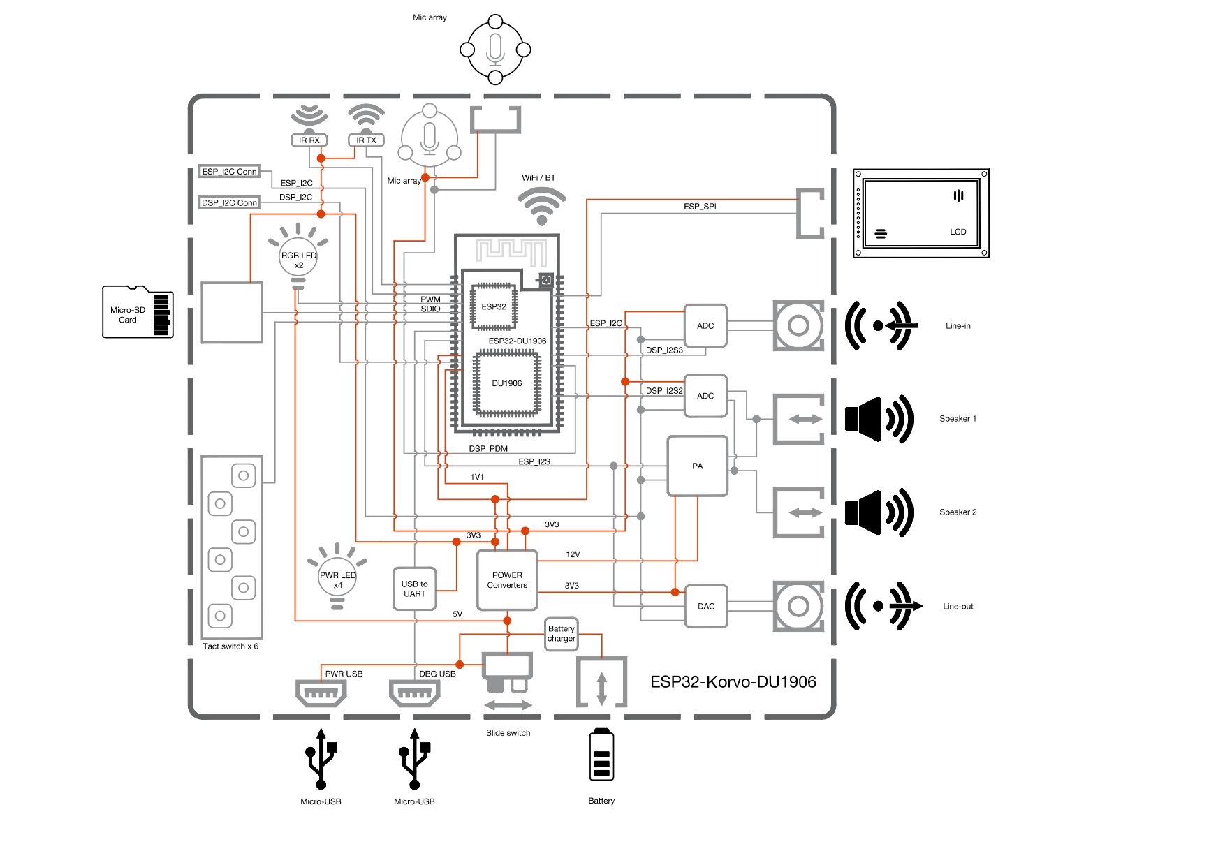
The block diagram below presents main components of the ESP32-Korvo-DU1906 and interconnections between components.

ESP32-Korvo-DU1906 Block Diagram (click to enlarge)
Description of Components
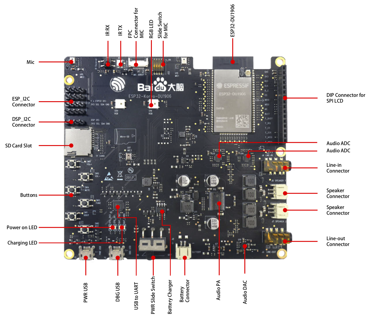
The following list and figure describe key components, interfaces and controls of the ESP32-Korvo-DU1906 used in this guide. This covers just what is needed now. For additional details please refer to schematics provided in Related Documents.

ESP32-Korvo-DU1906 Components (click to enlarge)
Key Componenet |
Description |
|---|---|
ESP32-DU1906 |
This is a powerful, general-purpose, Wi-Fi/Bluetooth audio communication module, targeting a wide variety of applications ranging from low-power sensor networks to the most demanding tasks, such as voice encoding/decoding, music streaming and running voice assistant client SDK. |
DIP Connector for SPI LCD |
ESP32-Korvo-DU1906 has a 2.54 mm pitch connector to connect SPI LCD. |
Audio ADC (Audio Analog-to-Digital Converter) |
ESP32-Korvo-DU1906 includes two ES7243 high-efficiency ADCs, with one for the collection of Audio PA outputs, and another for the collection of Line-in outputs. Both ADCs can be used for AEC. |
Line-in/out Connector (Earphone Jacks) |
The two earphone jacks are used to connect to Line-out outputs of Audio DAC and Line-in inputs of Audio ADC respectively. When a device is plugged in the Line-out earphone jack of Audio DAC, the Audio PA on the ESP32-Korvo-DU1906 will be turned off. |
Speaker Connector |
Output sockets to connect two 4-ohm speakers to provide stereo sound via digital Audio PA. |
Audio DAC (Audio Digital-to-Analog Converter) |
ES7148 Stereo DAC is able to convert digital signals into analog audio outputs. |
Audio PA (Digital Audio Power Amplifier) |
TAS5805M is a high-efficiency stereo closed-loop D-type amplifier with low power dissipation and rich sound. It can convert audio digital signals into high-power analog audio outputs and transmit them to external speakers for playback. When the Line-out earphone jack of the audio DAC plugged into the device, the Digital Audio PA on the ESP32-Korvo-DU1906 will be turned off. |
Battery Connector |
Connect a battery. |
Battery Charger |
AP5056, a constant-current/constant-voltage linear power management chip, can be used for charging management to a single lithium-ion battery. |
PWR Slide Switch |
Power switch for the board, turn on/off the power supply. |
USB to UART |
CP2102N supports USB-to-UART conversion for easy download and debugging of software. |
DBG USB (Debugging USB) |
USB communication between PC and ESP32-DU1906 module. |
PWR USB (Power supply USB) |
Provide power supply for the whole system. It is recommended that the system be connected to an at least 5 V / 2 A power adapter for sufficient current supply. |
Charging LEDs |
Indicating battery state. When a battery is connected, BAT_CHRG LED will turn red (indicating the battery is charging), then BAT_STBY LED will turn green (indicating the charging is completed). If there is no battery connected, the BAT_CHRG and BAT_STBY LEDs will be red and green respectively by default. |
Power on LEDs |
Indicating power state. The two LEDs (SYS_3V3, SYS_5) will turn red when the board is powered on. |
Buttons |
ESP32-Korvo-DU1906 has four functional buttons, one Reset button and one Boot button. |
SD Card Slot |
Connect a standard TF card. |
ESP_I2C Connector/DSP_I2C Connnector |
Two sets of reserved I2C debugging interfaces for users to debug. |
Mic |
ESP32-Korvo-DU1906 has three on-board digital microphones. The pickup holes of the three microphones are distributed in equilateral pyramid shape with distances of 60 mm in between. Together with DSP, the Microphone Array is able to realize noise reduction, AEC, beam formation and detection. |
IR TX/RX (Infrared Transmitter/Receiver) |
ESP32-Korvo-DU1906 has one infrared transmitter and one infrared receiver, which can be used together with the remote control module of ESP32. |
FPC Connector for Mic |
ESP32-Korvo-DU1906 has two FPC connectors to connect the SPI LCD screen and external microphone arrays. |
RGB LED |
ESP32-Korvo-DU1906 has two RGB LEDs for users that can be configured as status behavior indicator. |
Slide Switch for Mic |
ESP32-Korvo-DU1906 has a reserved interface for an external Microphone Array sub-board. This switch needs to be toggled to OFF when using an external Microphone Array sub-board, and needs to be toggled to ON when using the on-board Microphone Array. |
Start Application Development
Before powering up the ESP32-Korvo-DU1906, please make sure that the board has been received in good condition with no obvious signs of damage.
Initial Setup
Prepare the board for loading of the first sample application:
Connect 4-ohm speakers to the two Speaker Connectors. Connecting earphones to the Line-out Connector is an option.
Plug in the Micro-USB cables to the PC and to both USB connectors of the ESP32-Korvo-DU1906.
Assuming that a battery is connected, the Charging LED (red) will keep the lights on.
Toggle left the PWR Slide Switch.
The red Power On LED should turn on.
If this is what you see on the LEDs, the board should be ready for application upload. Now prepare the PC by loading and configuring development tools what is discussed in the next section.
Develop Applications
Once the board is initially set up and checked, you can start preparing the development tools. The Section Development Boards will walk you through the following steps:
Set up ESP-IDF to get a common development framework for the ESP32 (and ESP32-S2) chips in C language;
Get ESP-ADF to install the API specific to audio applications;
Set up env to make the framework aware of the audio specific API;
Start a Project that will provide a sample audio application for the board;
Connect Your Device to prepare the application for loading;
Build the Project to finally run the application and play some music.
Contents and Packaging
Retail orders
If you order one or several samples, each board will come in a plastic package or other package chosen by the retailer.
For retail orders, please go to https://www.espressif.com/zh-hans/products/devkits/esp32-korvo-du1906.