ESP32-S2-Saola-1
The ESP32-S2-Saola-1 development board is one of Espressif’s official boards. This board is based on the ESP32-S2-WROVER module, with the ESP32-S2 as the core.
Specifications
Wi-Fi 802.11 b/g/n (802.11n up to 150 Mbps)
Built around ESP32-S2 series of SoCs Xtensa® single-core
Integrated 4 MB SPI flash
Integrated 2 MB PSRAM
- Peripherals
43 × programmable GPIOs
2 × 13-bit SAR ADCs, up to 20 channels
2 × 8-bit DAC
14 × touch sensing IOs
4 × SPI
1 × I2S
2 × I2C
2 × UART
RMT (TX/RX)
LED PWM controller, up to 8 channels
1 × full-speed USB OTG
1 × temperature sensor
1 × DVP 8/16 camera interface, implemented using the hardware resources of I2S
1 × LCD interface (8-bit serial RGB/8080/6800), implemented using the hardware resources of SPI2
1 × LCD interface (8/16/24-bit parallel), implemented using the hardware resources of I2S
1 × TWAI® controller (compatible with ISO 11898-1)
Onboard PCB antenna or external antenna connector
Header Block
Note
Not all of the chip pins are exposed to the pin headers.
J2
No. |
Name |
Type |
Function |
|---|---|---|---|
1 |
3V3 |
P |
3.3 V power supply |
2 |
IO0 |
I/O |
GPIO0, Boot |
3 |
IO1 |
I/O |
GPIO1, ADC1_CH0, TOUCH_CH1 |
4 |
IO2 |
I/O |
GPIO2, ADC1_CH1, TOUCH_CH2 |
5 |
IO3 |
I/O |
GPIO3, ADC1_CH2, TOUCH_CH3 |
6 |
IO4 |
I/O |
GPIO4, ADC1_CH3, TOUCH_CH4 |
7 |
IO5 |
I/O |
GPIO5, ADC1_CH4, TOUCH_CH5 |
8 |
IO6 |
I/O |
GPIO6, ADC1_CH5, TOUCH_CH6 |
9 |
IO7 |
I/O |
GPIO7, ADC1_CH6, TOUCH_CH7 |
10 |
IO8 |
I/O |
GPIO8, ADC1_CH7, TOUCH_CH8 |
11 |
IO9 |
I/O |
GPIO9, ADC1_CH8, TOUCH_CH9 |
12 |
IO10 |
I/O |
GPIO10, ADC1_CH9, TOUCH_CH10 |
13 |
IO11 |
I/O |
GPIO11, ADC2_CH0, TOUCH_CH11 |
14 |
IO12 |
I/O |
GPIO12, ADC2_CH1, TOUCH_CH12 |
15 |
IO13 |
I/O |
GPIO13, ADC2_CH2, TOUCH_CH13 |
16 |
IO14 |
I/O |
GPIO14, ADC2_CH3, TOUCH_CH14 |
17 |
IO15 |
I/O |
GPIO15, ADC2_CH4, XTAL_32K_P |
18 |
IO16 |
I/O |
GPIO16, ADC2_CH5, XTAL_32K_N |
19 |
IO17 |
I/O |
GPIO17, ADC2_CH6, DAC_1 |
20 |
5V0 |
P |
5 V power supply |
21 |
GND |
G |
Ground |
J3
No. |
Name |
Type |
Function |
|---|---|---|---|
1 |
GND |
G |
Ground |
2 |
RST |
I |
CHIP_PU, Reset |
3 |
IO46 |
I |
GPIO46 |
4 |
IO45 |
I/O |
GPIO45 |
5 |
IO44 |
I/O |
GPIO44, U0RXD |
6 |
IO43 |
I/O |
GPIO43, U0TXD |
7 |
IO42 |
I/O |
GPIO42, MTMS |
8 |
IO41 |
I/O |
GPIO41, MTDI |
9 |
IO40 |
I/O |
GPIO40, MTDO |
10 |
IO39 |
I/O |
GPIO39, MTCK |
11 |
IO38 |
I/O |
GPIO38 |
12 |
IO37 |
I/O |
GPIO37 |
13 |
IO36 |
I/O |
GPIO36 |
14 |
IO35 |
I/O |
GPIO35 |
16 |
IO34 |
I/O |
GPIO34 |
17 |
IO33 |
I/O |
GPIO33 |
17 |
IO26 |
I/O |
GPIO26 |
18 |
IO21 |
I/O |
GPIO21 |
19 |
IO20 |
I/O |
GPIO20, ADC2_CH3, USB_D+ |
20 |
IO19 |
I/O |
GPIO19, ADC2_CH3, USB_D- |
21 |
IO18 |
I/O |
GPIO18, ADC2_CH3, DAC_2 |
P: Power supply; I: Input; O: Output; T: High impedance.
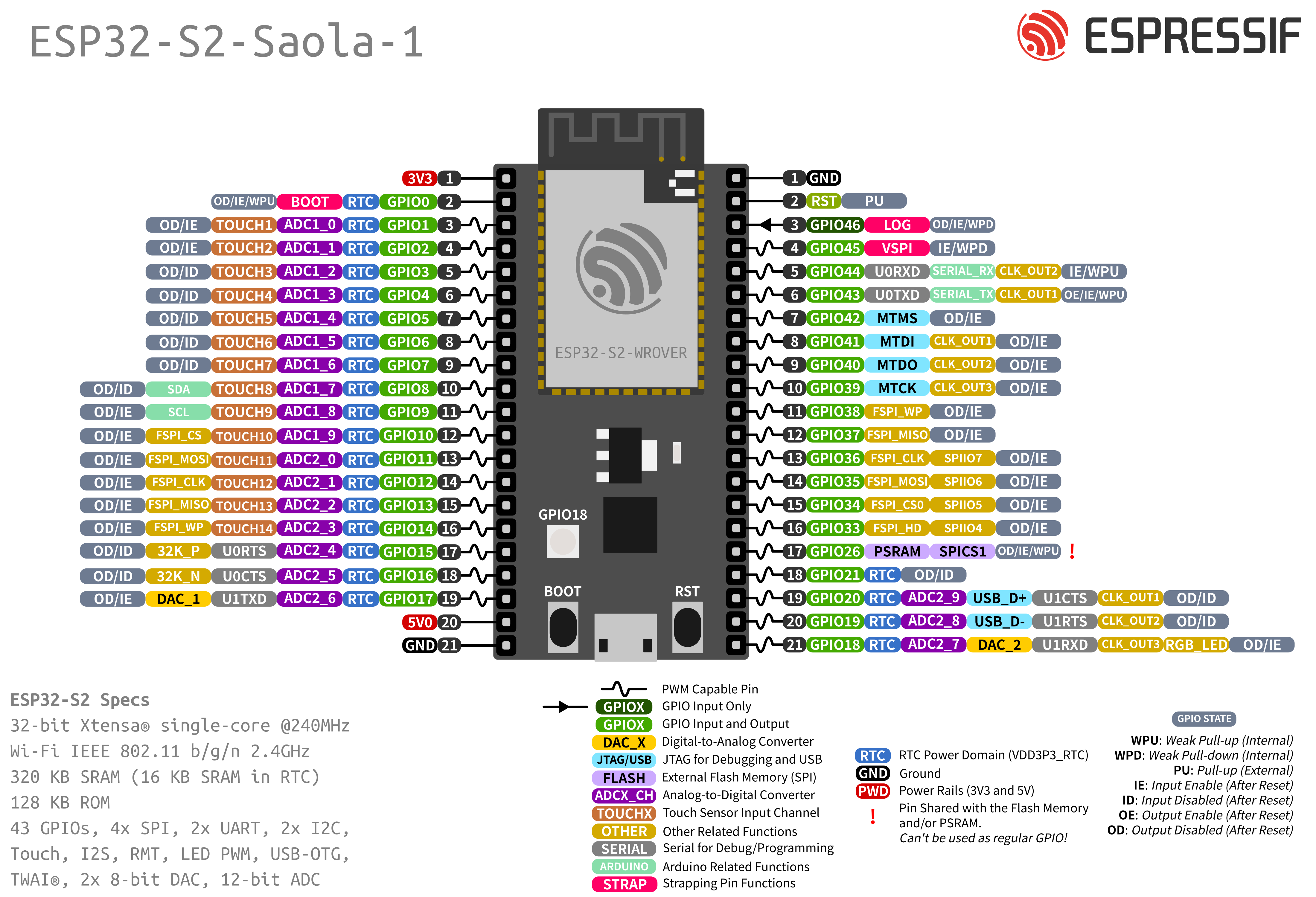
Pin Layout
Strapping Pins
Some of the GPIO’s have important features during the booting process. Here is the list of the strapping pins on the ESP32-S2.
GPIO |
Default |
Function |
Pull-up |
Pull-down |
|---|---|---|---|---|
IO45 |
Pull-down |
Voltage of Internal LDO (VDD_SDIO) |
1V8 |
3V3 |
IO0 |
Pull-up |
Booting Mode |
SPI Boot |
Download Boot |
IO46 |
Pull-down |
Booting Mode |
Don’t Care |
Download Boot |
IO46 |
Pull-up |
Enabling/Disabling Log Print During Booting and Timing of SDIO Slave |
U0TXD Active |
U0TXD Silent |
For more detailed information, see the ESP32-S2 datasheet.
Restricted Usage GPIOS
Some of the GPIO’s are used for the external flash and PSRAM. These GPIO’s cannot be used:
GPIO |
Shared Function |
|---|---|
IO26 |
Connected to PSRAM |
Other GPIO’s are INPUT ONLY and cannot be used as output pin:
GPIO |
Function |
|---|---|
IO46 |
GPIO46 |
Resources
ESP32-S2 (Datasheet)
ESP32-S2-WROVER (Datasheet)
ESP32-S2-Saola-1 (Schematics)