ESP32-MeshKit-Sense Hardware Design Guidelines
1. Overview
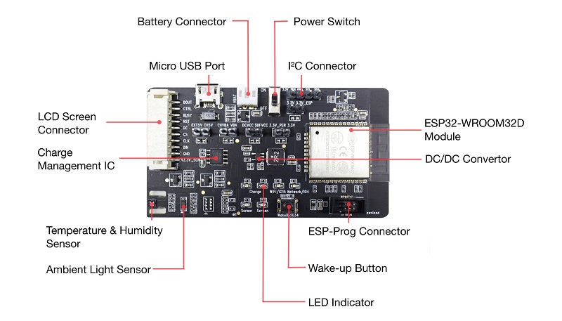
ESP32-MeshKit-Sense is a development board with an ESP32 module at its core. It features peripherals, such as a temperature and humidity sensor, an ambient light sensor, etc. The board can be interfaced with screens. The board is mainly used to detect the current consumption of ESP32 modules in a normal operation state or in sleep mode, when connected to different peripherals.
For more information on ESP32, please refer to ESP32 Datasheet.
2. Block Diagram and PCB Layout
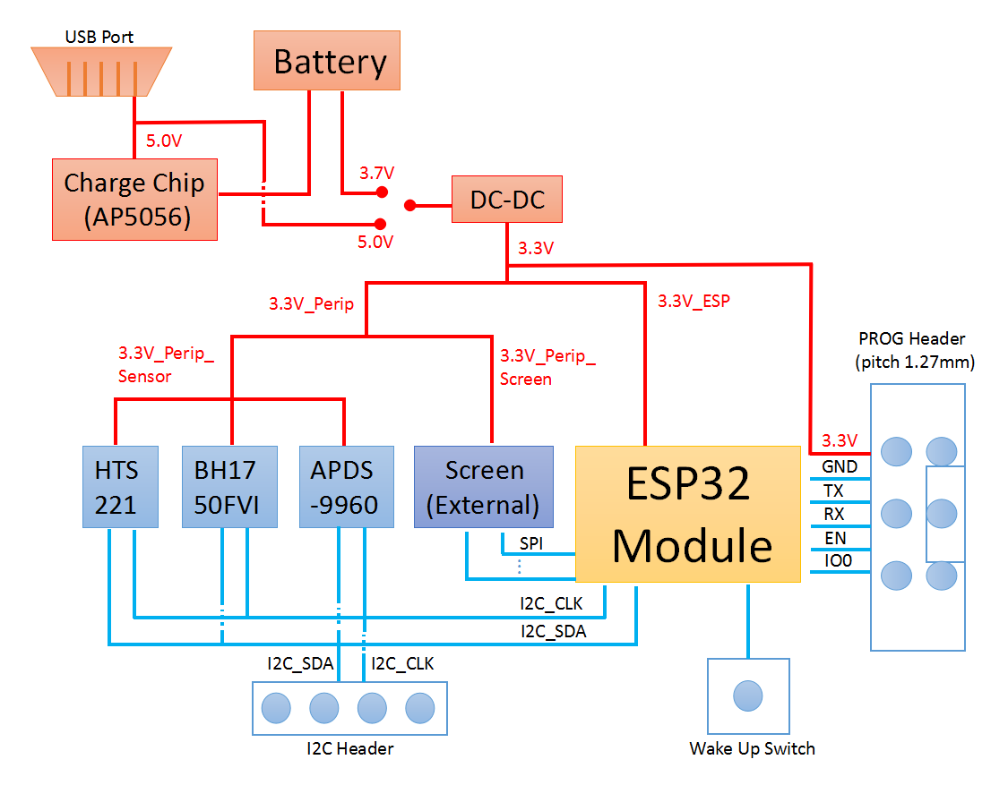
2.1 Block Diagram
The figure below shows the block diagram of ESP32.
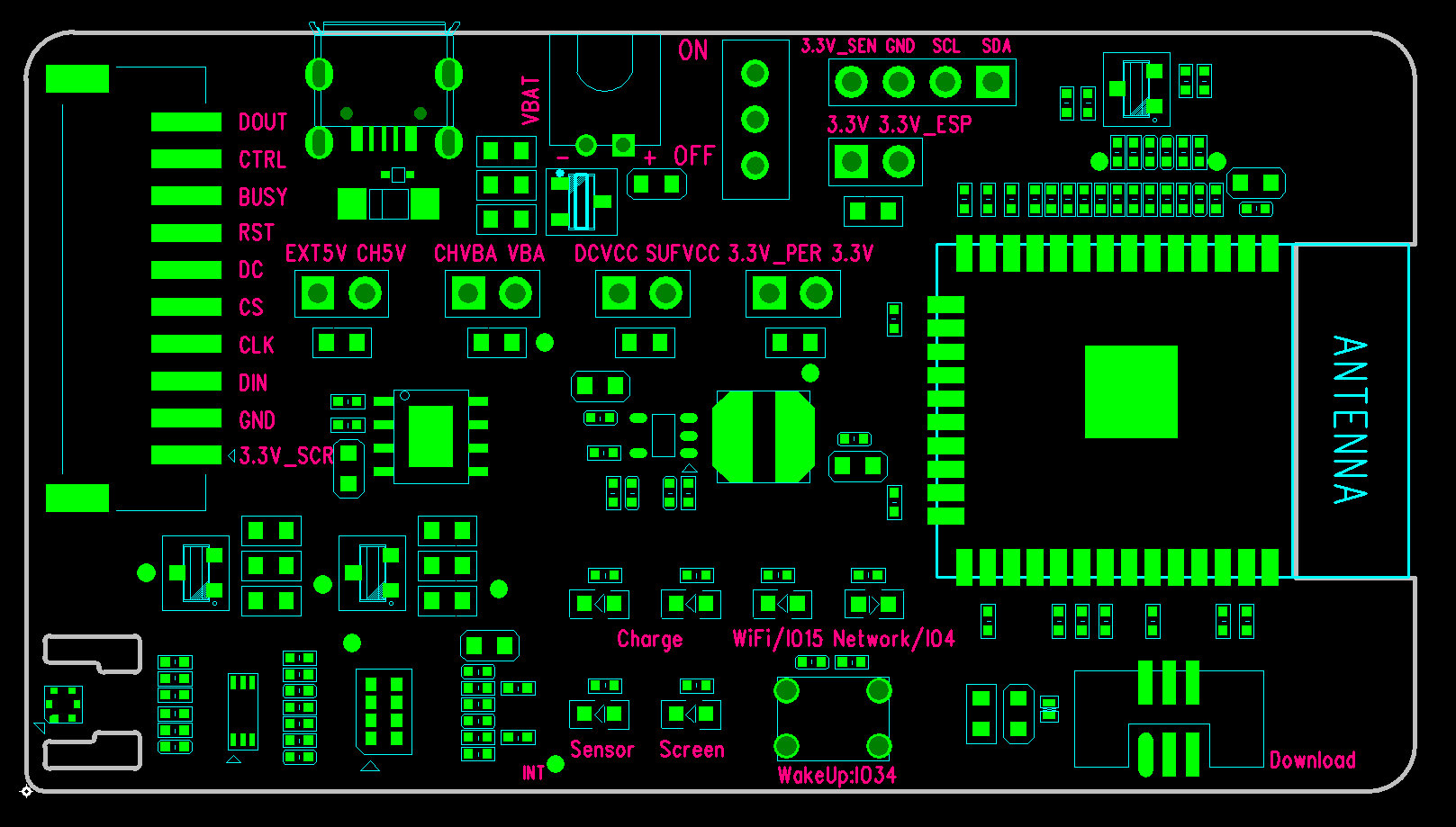
2.2 PCB Layout
The figure below shows the layout of ESP32-MeshKit-Sense PCB.
PCB Elements |
Description |
|---|---|
EXT5V |
5V input from USB |
CH5V |
input from the electrical charging chip |
CHVBA |
output from the electrical charging chip |
VBA |
Connects to the positive electrode of the battery |
SUFVCC |
When the switch is toggled to the ”ON” position, it is connected to the power input. When the switch is toggled to the ”OFF” position, the power supply is disconnected. |
DCVCC |
Input from power management chip DC-DC |
3.3V |
3.3V power output from power supply management chip |
3.3V_PER |
3.3V power supply for all peripherals |
3.3V_ESP |
3.3V power supply for all ESP32 modules |
3.3V_SEN |
3.3V power supply for the three on-board sensors |
3.3V_SCR |
3.3V power supply for the off-board screen |
Charge |
Battery charging indicator, D5 is a red light, indicating that charging is undergoing; D6 is a green light, indicating that charging is complete. |
Sensor |
Power indicator, indicating that 3.3V_Perip_Sensor is enabled |
Screen |
Power indicator, indicates that 3.3V_Perip_Screen is enabled |
WiFi / IO15 |
Signal indicator, indicating that Wi-Fi connection is working properly |
Network / IO4 |
Signal indicator, indicating the board is properly connected to the server |
3. Functional Modules
This chapter mainly introduces each functional module (interface) and the hardware schematics for them.
3.1 Power Supply Management Module
3.1.1 Power Supply Management Module
- orphan
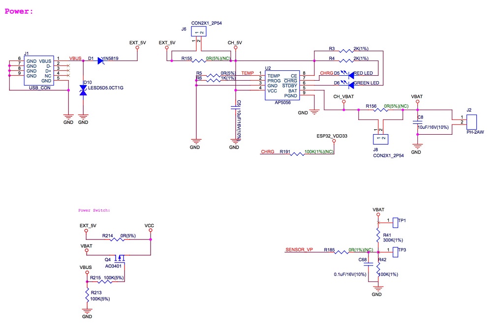
The development board can be powered by battery and the AP5056 power supply management chip can be used to charge the battery. The AP5056 is a complete constant current constant voltage linear charger for single cell lithium-ion batteries. It has 4.2V of preset charge voltage and 1A of programmable charge current.
When both the USB power supply and the battery power supply are available, the system selection of power supply will be: VBUS is high, Q4 is in cut-off state, VBAT (battery power) is automatically cut off from the system power supply, and the USB supplies power for the system.
The figure below shows the schematics for USB/BAT power supply management.
3.1.2 Power Supply Management for Peripherals
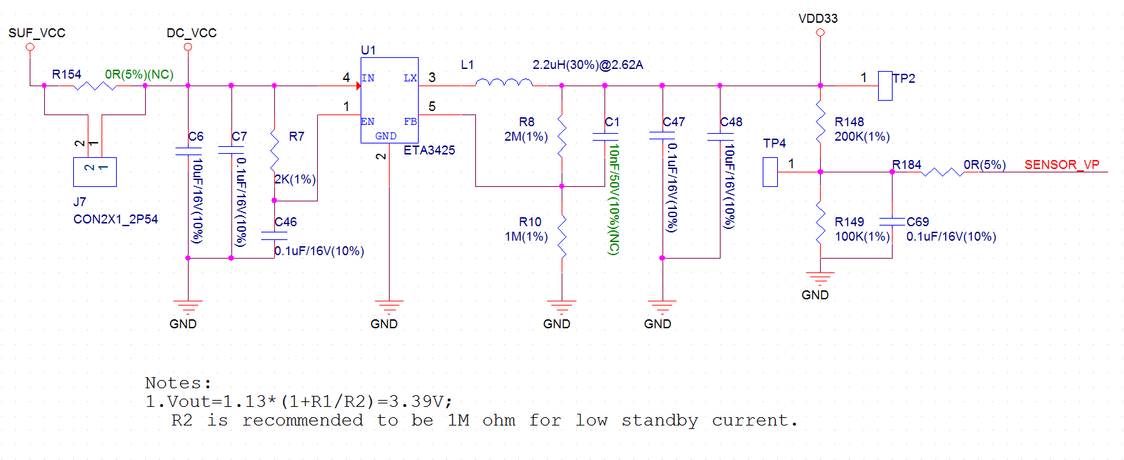
First of all, the input from the USB or BAT is converted by the power management chip into a 3.3V voltage to power the circuit. The power management chip on the board is ETA3425, which has an output voltage of 3.3V and a maximum output current of 600 mA.
The figure below shows the schematics for peripheral power supply.
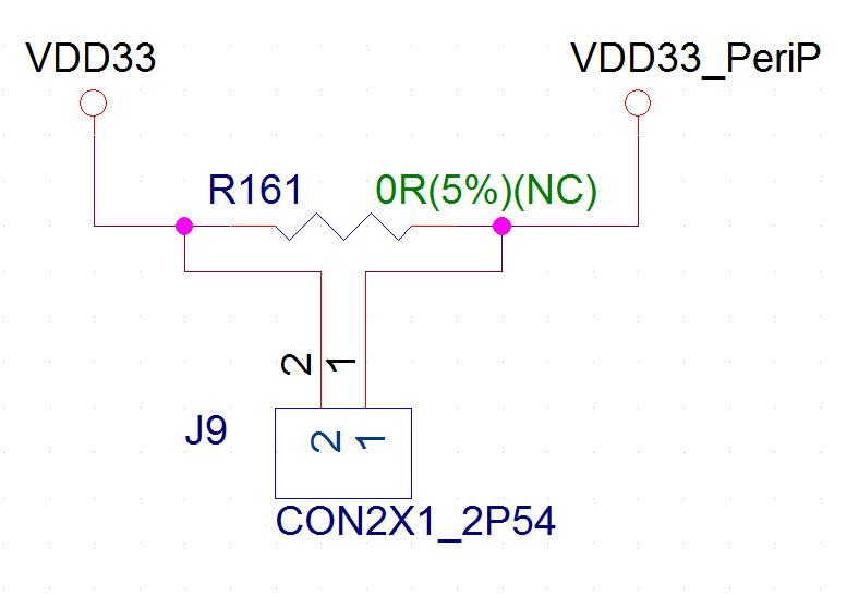
The main VDD33 circuit has two branches: One is ESP32_VDD33, which is used to power the ESP32 module module. The other VDD33_PeriP, which is used to power all peripherals. The connection between them can be controlled via the pin header and jumper cap.
The figure below shows the schematics for ESP32_VDD33.
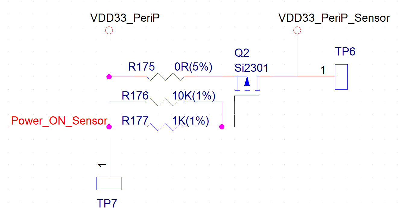
The VDD33_PeriP branch circuit also has two sub-branches: One is VDD33_PeriP_Screen, dedicated power supply for the external screen; and another is VDD33_PeriP_Sensor, power supply for the three sensors. The connection of the two can be controlled by the module GPIO+MOS.
The figure below shows the schematics for VDD33_PeriP.
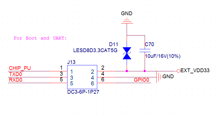
3.2 Boot & UART
The development board is integrated with a PROG Header, which can be connected to a ESP-PROG development board via a cable. Users can then connect the Micro USB of the ESP-PROG development board to a PC for ESP32-MeshKit-Sense firmware download and debugging.
The figure below shows the schematics for Boot & UART Circuit.
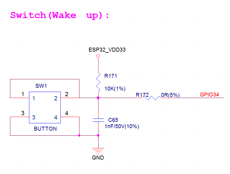
3.3 Module for Wakeup from Sleep
The board has a button connected to the pin IO34, which is a pin in the RTC domain. When the chip is in sleep, pressing the button will wake up ESP32.
The figure below shows the schematics for wakeup-from-sleep module.
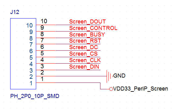
3.4 External Screens
The development board is integrated with a screen connector that can connect different external screens to the board via cables.
The figure below shows the schematics for external screens.
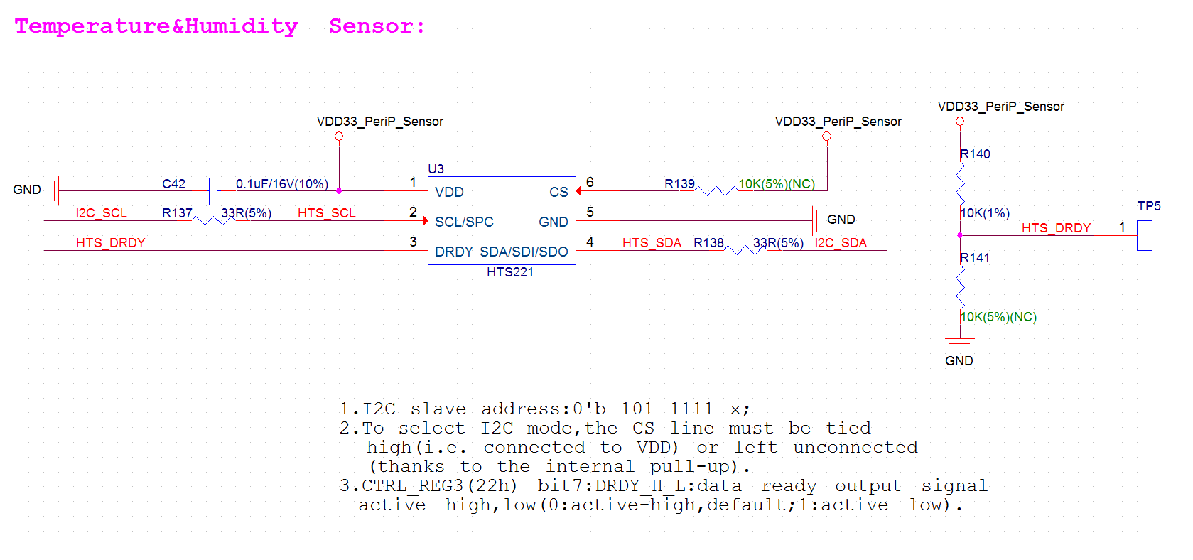
3.5 Sensors
3.5.1 Temperature and Humidity Sensor
The HTS221 is an ultra-compact sensor for relative humidity and temperature. A 3.3V power supply and I2C interface on the board are dedicated to HTS221.
The figure below shows the schematics for the temperature and humidity sensor.
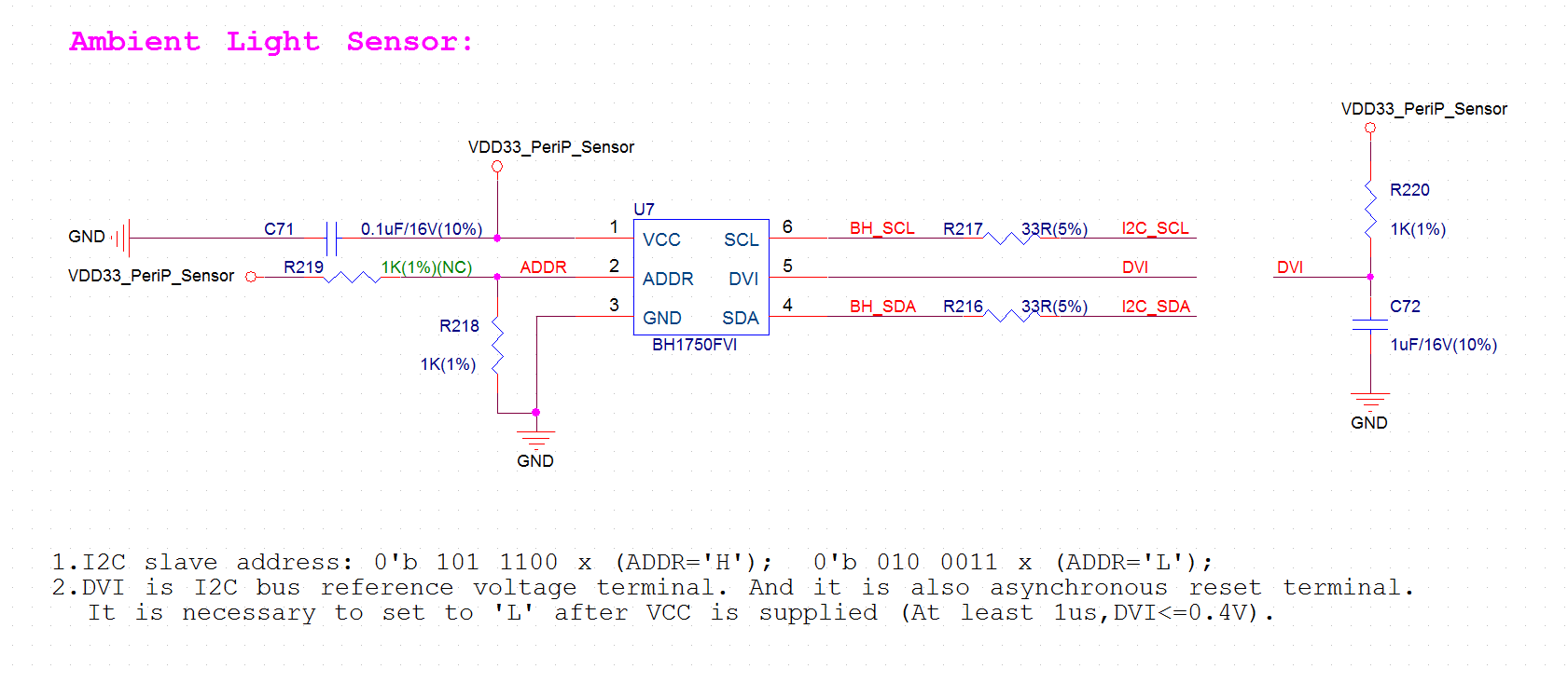
3.5.2 Ambient Light Sensor
The BH1750FVI is a digital ambient light sensor. A 3.3V power supply and I2C interface on the board are dedicated to HTS221.
The figure below shows the schematics for the ambient light sensor.
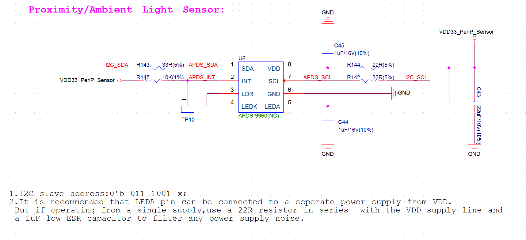
3.5.3 Ambient Brightness Sensor
The APDS-9960 is a ambient brightness sensor featuring advanced gesture detection, proximity detection, digital Ambient Light Sense (ALS) and Color Sense (RGBC). It also incorporates an IR LED driver. The development board uses 3.3V power supply and I2C interface. It should be noted that this device is not surface-mounted by default.
The figure below shows the schematics for the ambient brightness sensor.