Introduction to the ESP-Prog Board
1. Overview
ESP-Prog is one of Espressif’s development and debugging tools, with functions including automatic firmware downloading, serial communication, and JTAG online debugging. ESP-Prog’s automatic firmware downloading and serial communication functions are supported on both the ESP8266 and ESP32 platforms, while the JTAG online debugging is supported only on the ESP32 platform.
ESP-Prog can easily connect to a PC with the use of only one USB cable. Then, the PC can identify the board’s downloading and JTAG interfaces (functions) by their port numbers.
Given that the power supply voltage may vary on different user boards, either of the ESP-Prog interfaces can provide the 5V or the 3.3V power supply through pin headers, in order to ensure power compatibility.
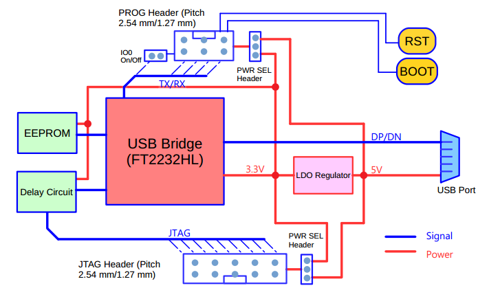
2. System Diagram
ESP-Prog’s overall functional block diagram is displayed below:
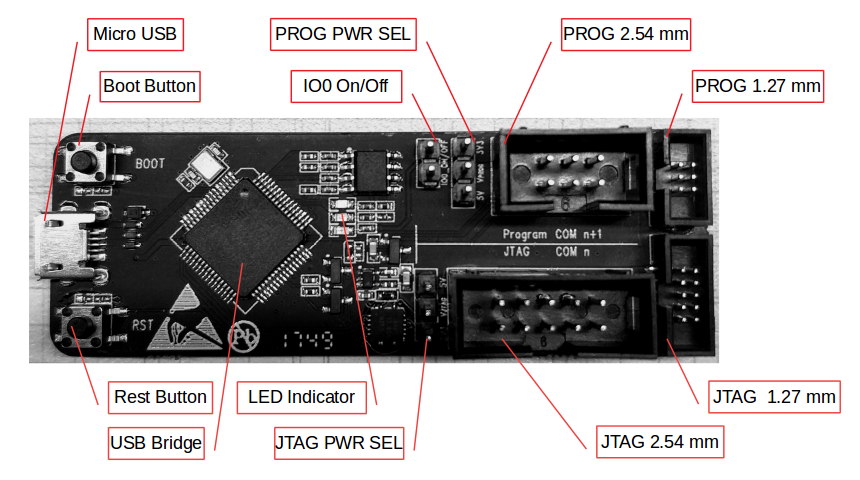
3. Hardware Introduction
The figure below describes the areas of each function on the ESP-Prog board.
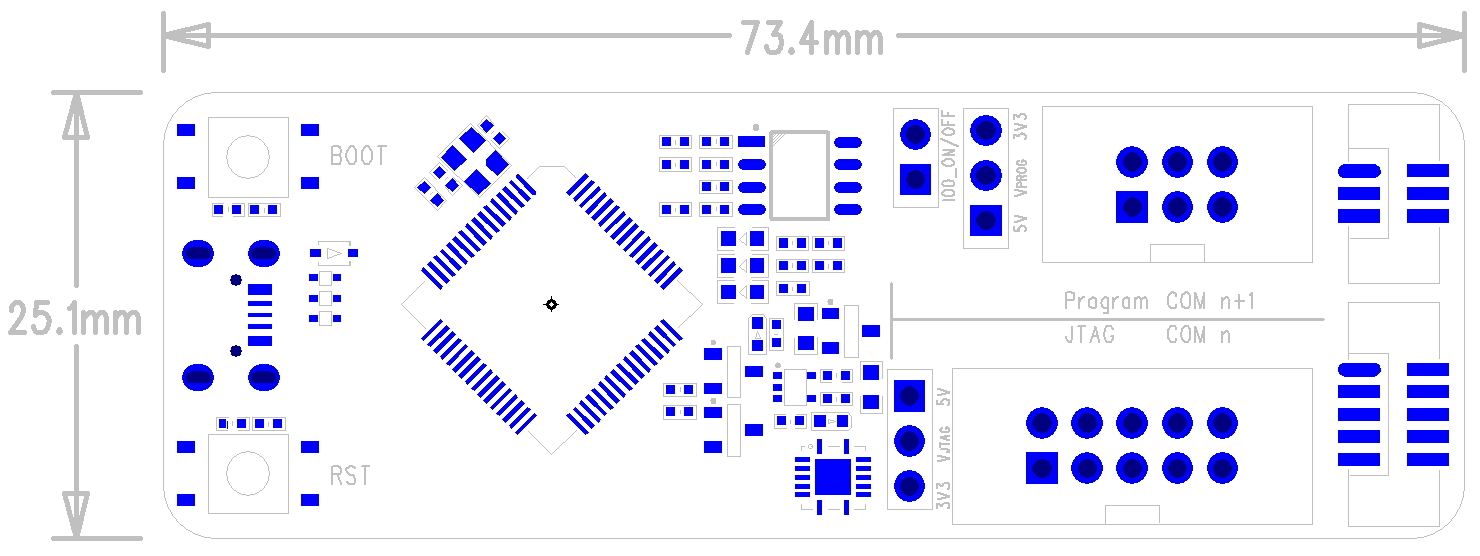
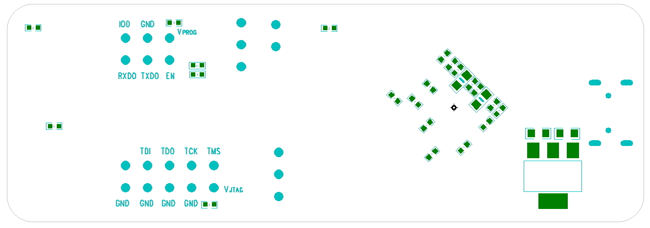
3.1. PCB Layout and Dimensions
ESP-Prog’s PCB layout is displayed below, showing the board’s dimensions and its interface markings. Please refer to Espressif website for the hardware resources including schematics, PCB reference design, BOM and other files.
Top side
Bottom side
3.2. Introduction to Functions
3.2.1. The Working Mode of USB Bridge
ESP-Prog uses FT2232HL, which is provided by FTDI, as its USB Bridge Controller chip. The board can be configured to convert the USB 2.0 interface to serial and parallel interfaces that support a wide range of industry standards. ESP-Prog uses FT2232HL’s default dual-asynchronous serial interface mode, allowing users to use the board easily by installing the FT2232HLdriver on their PCs.
Note
The PC is able to identify the ESP-Prog’s two ports by their port numbers. The bigger port number represents the Program interface, while the other one represents the JTAG interface.
3.2.2. Communication Interface
ESP-Prog can connect to ESP32 user boards, using both the Program interface and the JTAG interface. Users should connect the user board interfaces in a way that corresponds to the ESP-Prog board.
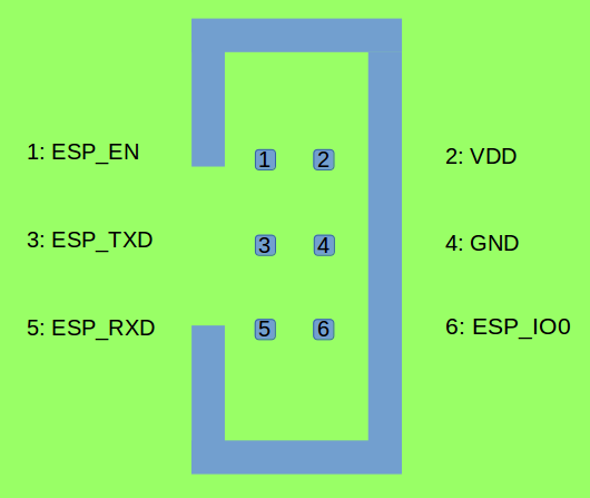
Program Interface The Program interface has six pins, including the UART interface (TXD, RXD), boot mode selection pin (ESPIO0) and reset pin (ESPEN). The design for the Program interface on the user board should follow the reference provided in the figure below.
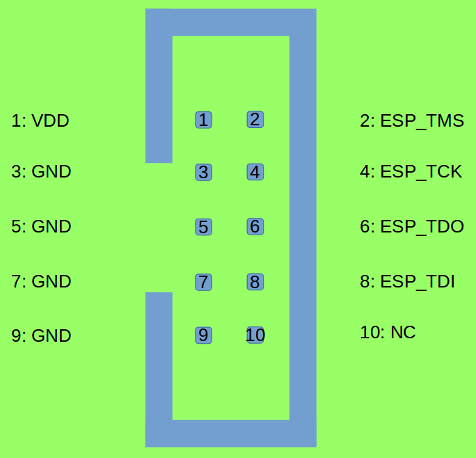
JTAG Interface The design for the JTAG interface on the user board should follow the reference provided in the figure below.
Fool-proof Design The ESP-Prog board uses header connectors (DC3-6P / DC3-10P) which support reverse-current circuitry protection. In such cases, it is recommended that users also use header connectors on their user boards, such as
FTSH-105-01-S-DV-*orDC3-*P.
Note
The flat cables used here are directional. Please use the cables provided by Espressif.
3.2.3. Automatic Downloading Function
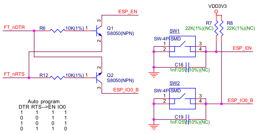
ESP-Prog supports automatic downloading. After connecting the Program interface of ESP-Prog to the user board, the downloading program can download data or run programs automatically by controlling the states of the start-mode selection pin (ESPIO0) and reset pin (ESPEN), which spares the users from manually restarting the device and selecting the downloading modes. The two buttons on the ESP-Prog board enable users to reset and control the boot mode of the device manually.
The schematics of the automatic downloading circuit is displayed below.
3.2.4. Delay Circuit
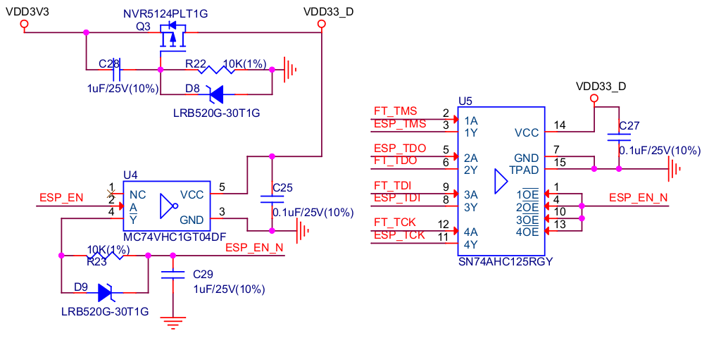
The delay circuit of ESP-Prog includes the bus buffer, inverter, MOS tube, first-order RC circuit, and other components. This delay circuit ensures that the ESP32 chip can power up or reset itself, before connecting with the JTAG signal, thus protecting the chip from the influence of JTAG on power-up or reset.
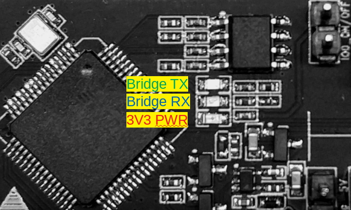
3.2.5. LED Status Indication
The red LED lights up when the system is connected to the 3.3V power;
The green LED lights up when ESP-Prog is downloading data to ESP32;
The blue LED lights up when ESP-Prog is receiving data from ESP32.
3.2.6. Pin Headers
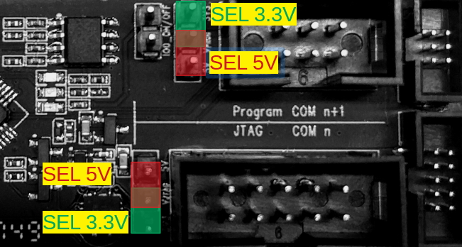
Users can choose either the 3.3V or 5V power supply for the Program and JTAG interfaces, using the pin headers shown in the figure below.
Pin header to select power supply The pin header in the middle is the power input pin for each interface. When this pin is connected to 5V, the power output of the interface is 5V. When this pin is connected to 3.3V, the power output of the interface is 3.3V.
IO0 On/Off Pin Pin IO0 can be set to select ESP8266’s and ESP32’s boot modes. This pin can be used as a common GPIO, after the chip is powered on. Users can then disconnect Pin IO0 manually to protect the operation of the user board from the influence of ESP-Prog’s automatic downloading circuit.
4. Step by Step Instruction
Connect the ESP-Prog board and the PC USB port via a USB cable.
Install the FT2232HL chip driver on your PC. The PC then detects the two ports of ESP-Prog, indicating that the driver has been installed successfully.
Select the output power voltage for the Program / JTAG interfaces, using pin headers.
Connect the ESP-Prog and ESP user boards with the gray flat cables provided by Espressif.
Start automatic downloading or JTAG debugging, using the official software tools or scripts provided by Espressif.
5. Useful Links
How to buy: espressif_systems (WeChat Account), Purchase consulting