ESP32-PICO-KIT V3 Getting Started Guide
This user guide shows how to get started with the ESP32-PICO-KIT V3 mini development board. For description of other versions of the ESP32-PICO-KIT check ESP32 H/W 硬件参考.
What You Need
- 1 × ESP32-PICO-KIT V3 mini development board
- 1 × USB A / Micro USB B cable
- 1 × PC loaded with Windows, Linux or Mac OS
Overview
ESP32-PICO-KIT V3 is a mini development board based on the ESP32-PICO-D4 SIP module produced by Espressif. All the IO signals and system power on ESP32-PICO-D4 are led out through two standard 20 pin x 0.1” pitch headers on both sides for easy interfacing. The development board integrates a USB-UART Bridge circuit, allowing the developers to connect the development board to a PC’s USB port for downloads and debugging.
Functional Description
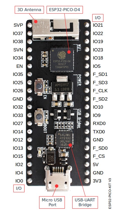
The following list and figure below describe key components, interfaces and controls of ESP32-PICO-KIT V3 board.
- ESP32-PICO-D4
- Standard ESP32-PICO-D4 module soldered to the ESP32-PICO-KIT V3 board. The complete system of the ESP32 chip has been integrated into the SIP module, requiring only external antenna with LC matching network, decoupling capacitors and pull-up resistors for EN signals to function properly.
- USB-UART Bridge
- A single chip USB-UART bridge provides up to 1 Mbps transfers rates.
- I/O
- All the pins on ESP32-PICO-D4 are broken out to the pin headers on the board. Users can program ESP32 to enable multiple functions such as PWM, ADC, DAC, I2C, I2S, SPI, etc.
- Micro USB Port
- USB interface. It functions as the power supply for the board and the communication interface between PC and ESP32-PICO-KIT V3.
- EN Button
- Reset button; pressing this button resets the system.
- BOOT Button
- Holding down the Boot button and pressing the EN button initiates the firmware download mode. Then user can download firmware through the serial port.

ESP32-PICO-KIT V3 board layout