ESP32-PICO-KIT V3 Getting Started Guide
This guide shows how to get started with the ESP32-PICO-KIT V3 mini development board. For the description of other ESP32-PICO-KIT versions, please check ESP32 Hardware Reference.
What You Need
- ESP32-PICO-KIT V3 mini development board
- USB 2.0 A to Micro B cable
- Computer running Windows, Linux, or macOS
You can skip the introduction sections and go directly to Section Start Application Development.
Overview
ESP32-PICO-KIT V3 is an ESP32-based mini development board produced by Espressif. The core of this board is ESP32-PICO-D4 - a System-in-Package (SiP) module.
The development board features a USB-UART Bridge circuit, which allows developers to connect the board to a computer’s USB port for flashing and debugging.
All the IO signals and system power on ESP32-PICO-D4 are led out to two rows of 20 x 0.1” header pads on both sides of the development board for easy access.
Functional Description
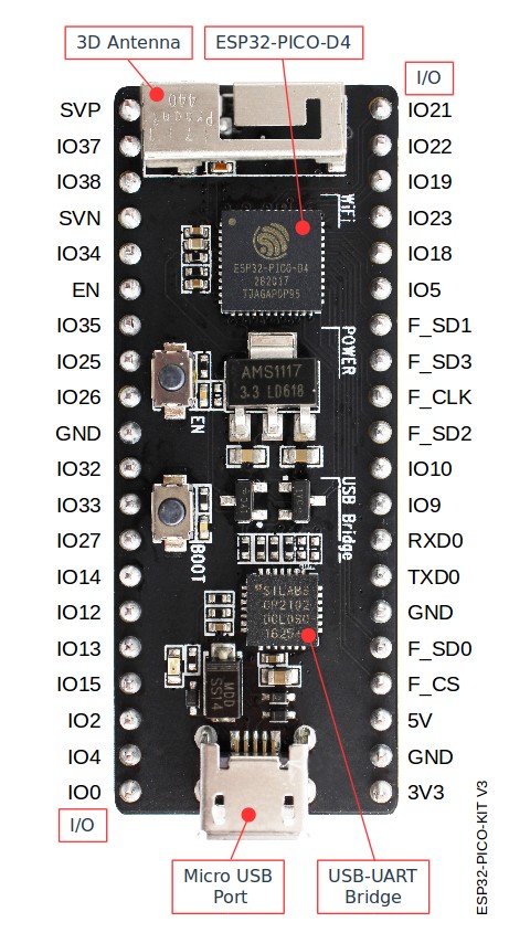
The following figure and the table below describe the key components, interfaces, and controls of the ESP32-PICO-KIT V3 board.

ESP32-PICO-KIT V3 board layout
Below is the description of the items identified in the figure starting from the top left corner and going clockwise.
| Key Component | Description |
|---|---|
| ESP32-PICO-D4 | Standard ESP32-PICO-D4 module soldered to the ESP32-PICO-KIT V3 board. The complete ESP32 system on a chip (ESP32 SoC) has been integrated into the SiP module, requiring only an external antenna with LC matching network, decoupling capacitors, and a pull-up resistor for EN signals to function properly. |
| LDO | 5V-to-3.3V Low dropout voltage regulator (LDO). |
| USB-UART bridge | Single-chip USB-UART bridge provides up to 1 Mbps transfers rates. |
| Micro USB Port | USB interface. Power supply for the board as well as the communication interface between a computer and the board. |
| Power On LED | This red LED turns on when power is supplied to the board. |
| I/O | All the pins on ESP32-PICO-D4 are broken out to pin headers. You can program ESP32 to enable multiple functions, such as PWM, ADC, DAC, I2C, I2S, SPI, etc. |
| BOOT Button | Download button. Holding down Boot and then pressing EN initiates Firmware Download mode for downloading firmware through the serial port. |
| EN Button | Reset button. |
Start Application Development
Before powering up your ESP32-PICO-KIT V3, please make sure that the board is in good condition with no obvious signs of damage.
After that, proceed to ESP32 Hardware Reference, where Section Installation Step by Step will quickly help you set up the development environment and then flash an example project onto your board.