ESP32-Ethernet-Kit V1.0 Getting Started Guide
This guide shows how to get started with the ESP32-Ethernet-Kit development board and also provides information about its functionality and configuration options.
The ESP32-Ethernet-Kit is an Ethernet-to-Wi-Fi development board that enables Ethernet devices to be interconnected over Wi-Fi. At the same time, to provide more flexible power supply options, the ESP32-Ethernet-Kit also supports power over Ethernet (PoE).
What You Need
- ESP32-Ethernet-Kit V1.0 board
- USB 2.0 A to Micro B Cable
- Computer running Windows, Linux, or macOS
You can skip the introduction sections and go directly to Section Start Application Development.
Overview
ESP32-Ethernet-Kit is an ESP32-based development board produced by Espressif.
It consists of two development boards, the Ethernet board A and the PoE board B, The Ethernet board (A) contains Bluetooth / Wi-Fi dual-mode ESP32-WROVER-B module and IP101GRI, a Single Port 10/100 Fast Ethernet Transceiver (PHY). The PoE board (B) provides power over Ethernet functionality. The A board can work independently, without the board B installed.
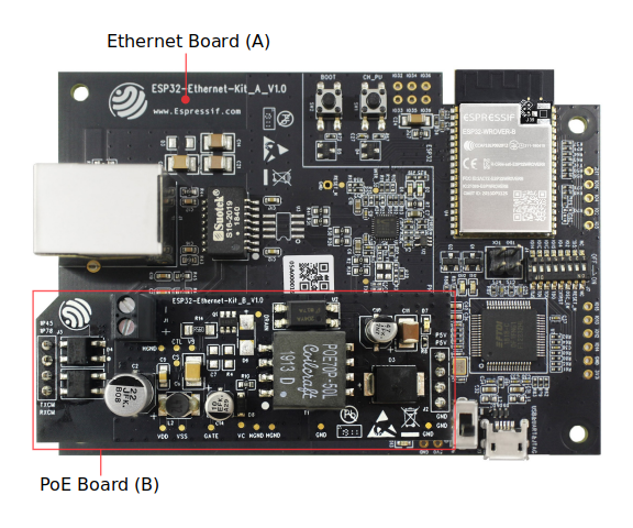
ESP32-Ethernet-Kit V1.0
For the application loading and monitoring the Ethernet board (A) also features FTDI FT2232H chip - an advanced multi-interface USB bridge. This chip enables to use JTAG for direct debugging of ESP32 through the USB interface without a separate JTAG debugger.
Functionality Overview
The block diagram below shows the main components of ESP32-Ethernet-Kit and their interconnections.
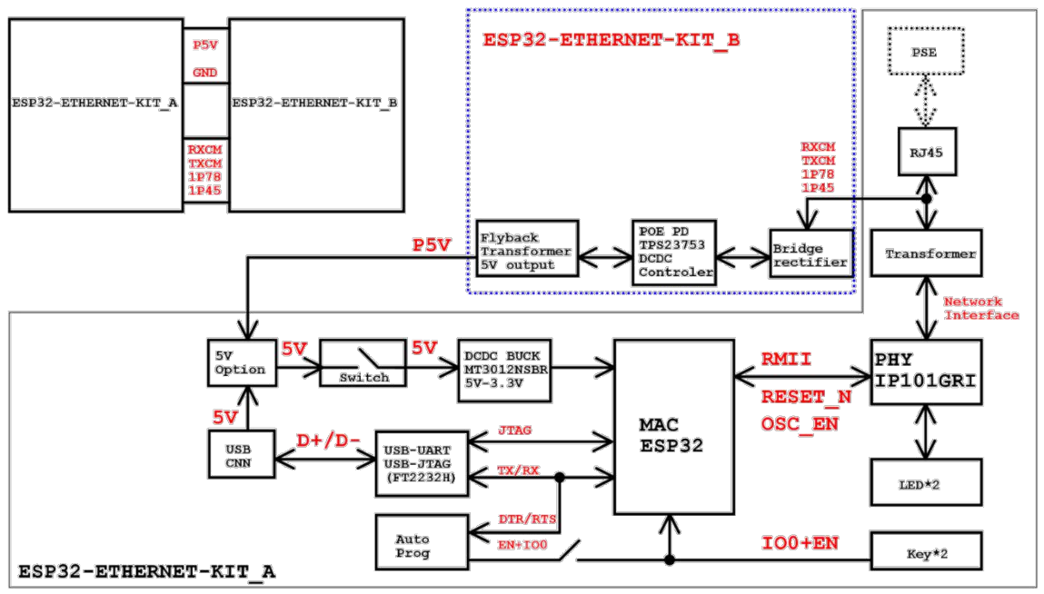
ESP32-Ethernet-Kit block diagram (click to enlarge)
Functional Description
The following two figures and tables describe the key components, interfaces, and controls of the ESP32-Ethernet-Kit.
Ethernet Board (A)
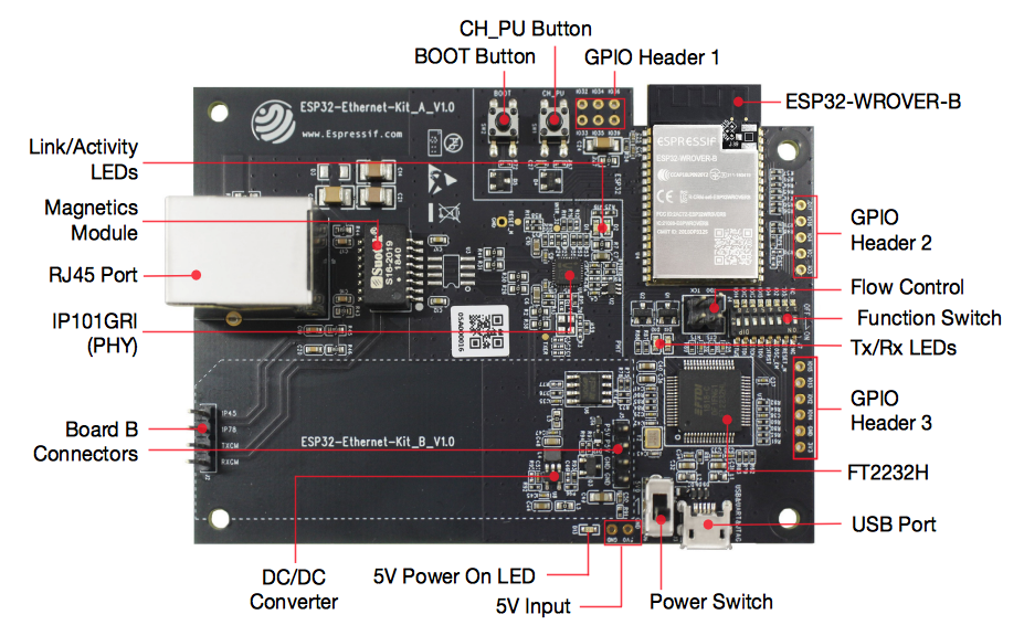
ESP32-Ethernet-Kit - Ethernet board (A) layout (click to enlarge)
The table below provides description starting from the picture’s top right corner and going clockwise.
| Key Component | Description |
|---|---|
| ESP32-WROVER-B | This ESP32 module features 64-Mbit PSRAM for flexible extended storage and data processing capabilities. |
| GPIO Header 2 | Five unpopulated through-hole solder pads to provide access to selected GPIOs of ESP32. For details, see GPIO Header 2. |
| Flow Control | A jumper header with access to the board signals. For details, see Flow Control. |
| Function Switch | A DIP switch used to configure the functionality of selected GPIOs of ESP32. For details, see Function Switch. |
| Tx/Rx LEDs | Two LEDs to show the status of UART transmission. |
| GPIO Header 3 | Provides access to some GPIOs of ESP32 that can be used depending on the position of the Function Switch. |
| FT2232H | The FT2232H chip serves as a multi-protocol USB-to-serial bridge which can be programmed and controlled via USB to provide communication with ESP32. FT2232H also features USB-to-JTAG interface which is available on channel A of the chip, while USB-to-serial is on channel B. The FT2232H chip enhances user-friendliness in terms of application development and debugging. See ESP32-Ethernet-Kit V1.0 Ethernet board (A) schematic. |
| USB Port | USB interface. Power supply for the board as well as the communication interface between a computer and the board. |
| Power Switch | Power On/Off Switch. Toggling toward the Boot button powers the board on, toggling away from Boot powers the board off. |
| 5V Input | The 5V power supply interface can be more convenient when the board is operating autonomously (not connected to a computer). |
| 5V Power On LED | This red LED turns on when power is supplied to the board, either from USB or 5V Input. |
| DC/DC Converter | Provided DC 5 V to 3.3 V conversion, output current up to 2A. |
| Board B Connectors | A pair male header pins for mounting the PoE board (B). |
| IP101GRI (PHY) | The physical layer (PHY) connection to the Ethernet cable is implemented using the IP101GRI chip. The connection between PHY and ESP32 is done through the reduced media-independent interface (RMII), a variant of the media-independent interface (MII) standard. The PHY supports the IEEE 802.3 / 802.3u standard of 10/100Mbps. |
| RJ45 Port | Ethernet network data transmission port. |
| Magnetics Module | The Magnetics are part of the Ethernet specification to protect against faults and transients, including rejection of common mode signals between the transceiver IC and the cable. The magnetics also provide galvanic isolation between the transceiver and the Ethernet device. |
| Link/Activity LEDs | Two LEDs (green and red) that respectively indicate the “Link” and “Activity” statuses of the PHY. |
| BOOT Button | Download button. Holding down BOOT and then pressing CH_PU initiates Firmware Download mode for downloading firmware through the serial port. |
| CH_PU Button | Reset button. |
| GPIO Header 1 | This header provides six unpopulated through-hole solder pads connected to spare GPIOs of ESP32. For details, see GPIO Header 1. |
PoE Board (B)
This board coverts power delivered over the Ethernet cable (PoE) to provide a power supply for the Ethernet board (A). The main components of the PoE board (B) are shown on the block diagram under Functionality Overview.
The PoE board (B) has the following features:
- Support for IEEE 802.3at
- Power output: 5 V, 1.4 A
To take advantage of the PoE functionality the RJ45 Port of the Ethernet board (A) should be connected with an Ethernet cable to a switch that supports PoE. When the Ethernet board (A) detects 5 V power output from the PoE board (B), the USB power will be automatically cut off.
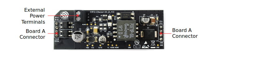
ESP32-Ethernet-Kit - PoE board (B) layout (click to enlarge)
| Key Component | Description |
|---|---|
| Board A Connector | Four female header pins for mounting this board onto Ethernet board (A). |
| External Power Terminals | Optional power supply to the PoE board (B). |
Setup Options
This section describes options to configure the ESP32-Ethernet-Kit hardware.
Function Switch
The functions for specific GPIO pins can be selected with the Function Switch.
| DIP SW | GPIO Pin | Pin Functionality if DIP SW is ON |
|---|---|---|
| 1 | GPIO14 | Connected to FT2232H to provide JTAG functionality |
| 2 | GPIO12 | Connected to FT2232H to provide JTAG functionality |
| 3 | GPIO13 | Connected to FT2232H to provide JTAG functionality |
| 4 | GPIO15 | Connected to FT2232H to provide JTAG functionality |
| 5 | GPIO4 | Connected to FT2232H to provide JTAG functionality |
| 6 | GPIO2 | Connected to on-board 25 MHz oscillator |
| 7 | GPIO5 | Connected to RESET_N input of IP101GRI |
| 8 | n/a |
You can make a certain GPIO pin available for other purposes by putting its DIP SW to the Off position.
Flow Control
This is a 2 x 2 jumper pin header intended for the UART flow control.
| . | Signal | Comment |
|---|---|---|
| 1 | MTDO | GPIO13, see also Function Switch |
| 2 | MTCK | GPIO15, see also Function Switch |
| 3 | RTS | RTS signal of FT2232H |
| 4 | CTS | CTS signal of FT2232H |
GPIO Allocation
This section describes allocation of ESP32 GPIOs to specific interfaces or functions of the ESP32-Ethernet-Kit.
IP101GRI (PHY) Interface
The allocation of the ESP32 (MAC) pins to IP101GRI (PHY) is shown in the table below. Implementation of ESP32-Ethernet-Kit defaults to Reduced Media-Independent Interface (RMII).
| . | ESP32 Pin (MAC) | IP101GRI (PHY) |
|---|---|---|
| RMII Interface | ||
| 1 | GPIO21 | TX_EN |
| 2 | GPIO19 | TXD[0] |
| 3 | GPIO22 | TXD[1] |
| 4 | GPIO25 | RXD[0] |
| 5 | GPIO26 | RXD[1] |
| 6 | GPIO27 | CRS_DV |
| 7 | GPIO0 | REF_CLK |
| Serial Management Interface | ||
| 8 | GPIO23 | MDC |
| 9 | GPIO18 | MDIO |
| PHY Reset | ||
| 10 | GPIO5 | Reset_N |
Note
Except for REF_CLK, the allocation of all pins under the RMII Interface is fixed and cannot be changed either through IOMUX or GPIO Matrix.
GPIO Header 1
This header exposes some GPIOs that are not used elsewhere on the ESP32-Ethernet-Kit.
| . | ESP32 Pin |
|---|---|
| 1 | GPIO32 |
| 2 | GPIO33 |
| 3 | GPIO34 |
| 4 | GPIO35 |
| 5 | GPIO36 |
| 6 | GPIO39 |
GPIO Header 2
This header contains the GPIOs with specific MII functionality (except GPIO2), as opposed to Reduced Media-Independent Interface (RMII) functionality implemented on ESP32-Ethernet-Kit board by default, see IP101GRI (PHY) Interface. Depending on the situation, if MMI is used, specific Ethernet applications might require this functionality.
| . | ESP32 Pin | MII Function | Comments |
|---|---|---|---|
| 1 | GPIO17 | EMAC_CLK_180 | See note 1 |
| 2 | GPIO16 | EMAC_CLK_OUT | See note 1 |
| 3 | GPIO4 | EMAC_TX_ER | |
| 4 | GPIO2 | n/a | See note 2 |
| 5 | GPIO5 | EMAC_RX_CLK | See note 2 |
Note
- The ESP32 pins GPIO16 and GPIO17 are not broken out to the ESP32-WROVER-B module and therefore not available for use. If you need to use these pins, please solder a module without SPIRAM memory inside, e.g. the ESP32-WROOM-32D or ESP32-SOLO-1.
- Functionality depends on the settings of the Function Switch.
GPIO Header 3
The functionality of GPIOs connected to this header depends on the settings of the Function Switch.
| . | ESP32 Pin |
|---|---|
| 1 | GPIO15 |
| 2 | GPIO13 |
| 3 | GPIO12 |
| 4 | GPIO14 |
| 5 | GND |
| 6 | 3V3 |
GPIO Allocation Summary
| ESP32-WROVER-B | IP101GRI | UART | JTAG | GPIO | Comments |
|---|---|---|---|---|---|
| S_VP | IO36 | ||||
| S_VN | IO39 | ||||
| IO34 | IO34 | ||||
| IO35 | IO35 | ||||
| IO32 | IO32 | ||||
| IO33 | IO33 | ||||
| IO25 | RXD[0] | ||||
| IO26 | RXD[1] | ||||
| IO27 | CRS_DV | ||||
| IO14 | TMS | IO14 | |||
| IO12 | TDI | IO12 | |||
| IO13 | RTS | TCK | IO13 | ||
| IO15 | CTS | TDO | IO15 | ||
| IO2 | IO2 | See notes 1 and 3 below | |||
| IO0 | REF_CLK | See notes 2 and 3 below | |||
| IO4 | nTRST | IO4 | |||
| IO16 | IO16 (NC) | See note 4 below | |||
| IO17 | IO17 (NC) | See note 4 below | |||
| IO5 | Reset_N | IO5 | |||
| IO18 | MDIO | ||||
| IO19 | TXD[0] | ||||
| IO21 | TX_EN | ||||
| RXD0 | RXD | ||||
| TXD0 | TXD | ||||
| IO22 | TXD[1] | ||||
| IO23 | MDC |
Note
- GPIO2 is used to enable external oscillator of the PHY.
- GPIO0 is a source of 50 MHz reference clock for the PHY. The clock signal is first inverted, to account for transmission line delay, and then supplied to the PHY.
- To prevent affecting the power-on state of GPIO0 by the clock output on the PHY side, the PHY external oscillator is enabled using GPIO2 after ESP32 is powered up.
- The ESP32 pins GPIO16 and GPIO17 are not broken out to the ESP32-WROVER-B module and therefore not available for use. If you need to use these pins, please solder a module without SPIRAM memory inside, e.g. the ESP32-WROOM-32D or ESP32-SOLO-1.
Start Application Development
Before powering up your ESP32-Ethernet-Kit, please make sure that the board is in good condition with no obvious signs of damage.
Initial Setup
- Set the Function Switch on the Ethernet board (A) to its default position by turning all the switches to ON.
- To simplify flashing and testing the application, do not install any jumpers and do not connect any signals to the board headers.
- The PoE board (B) can now be plugged in, but do not connect external power to it.
- Connect the Ethernet board (A) to the PC with a USB cable.
- Turn the Power Switch from GND to 5V0 position, the 5V Power On LED should light up.
Now to Development
Proceed to Get Started, where Section Installation Step by Step will quickly help you set up the development environment and then flash an example project onto your board.
Move on to the next section only if you have successfully completed all the above steps.
Configure and Load the Ethernet Example
After setting up the development environment and testing the board, you can configure and flash the ethernet/ethernet example. This example has been created for testing Ethernet functionality. It supports different PHY, including IP101GRI installed on ESP32-Ethernet-Kit V1.0 board.