ESP32-S3-USB-OTG
ESP32-S3-USB-OTG is a development board that focuses on USB-OTG function verification and application development. It is based on ESP32-S3 SoC, supports Wi-Fi and BLE 5.0 wireless functions, and supports USB host and USB device functions. It can be used to develop applications such as wireless storage devices, Wi-Fi network cards, LTE MiFi, multimedia devices, virtual keyboards and mice. The development board has the following features:
Onboard ESP32-S3-MINI-1-N8 module, with built-in 8 MB flash
Onboard USB Type-A host and device interface, with built-in USB interface switching circuit
Onboard USB to serial debugging chip (Micro USB interface)
Onboard 1.3-inch LCD color screen, supports GUI
Onboard SD card interface, compatible with SDIO and SPI interfaces
Onboard charging IC, can be connected to lithium battery
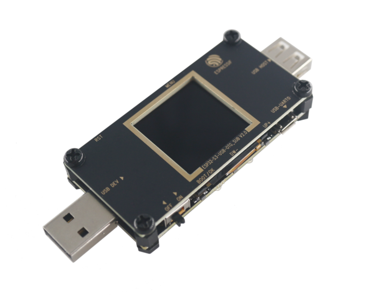
ESP32-S3-USB-OTG (click to enlarge)
The document consists of the following major sections:
Getting Started: Provides a brief overview of ESP32-S3-USB-OTG and necessary hardware and software information.
Hardware Reference: Provides detailed hardware information of ESP32-S3-USB-OTG.
Related Documents: Provides links to related documents.
Getting Started
This section describes how to start using ESP32-S3-USB-OTG. It includes introduction to basic information about ESP32-S3-USB-OTG first, and then on how to start using the development board for application development, as well as board packaging and retail information.
Description of Components
The ESP32-S3-USB-OTG development board includes the following parts:
Motherboard: ESP32-S3-USB-OTG motherboard is the core of the kit. The motherboard integrates the ESP32-S3-MINI-1 module and provides an interface of the 1.3-inch LCD screen.
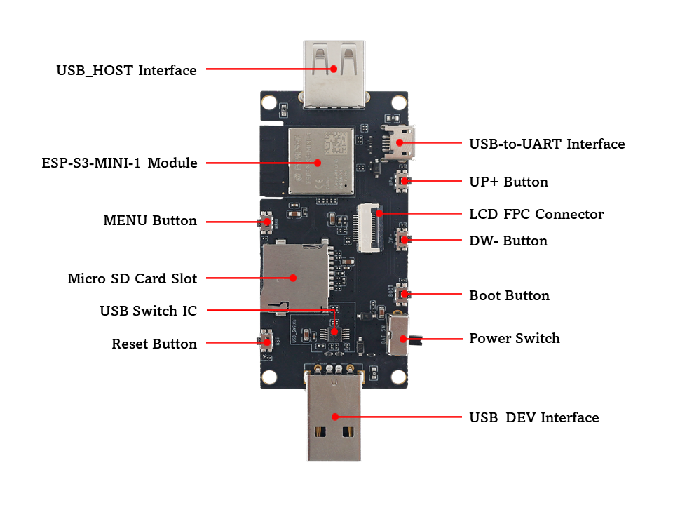
ESP32-S3-USB-OTG Top View (click to enlarge)
The following table starts with the USB_HOST Interface on the left, and introduces the main components in the above figure in an anticlockwise order.
Main components |
Description |
|---|---|
USB_HOST Interface |
USB Type-A female port, used to connect other USB devices. |
ESP32-S3-MINI-1 Module |
ESP32-S3-MINI-1 is a powerful, generic Wi-Fi + Bluetooth LE MCU module that has a rich set of peripherals. It has strong ability for neural network computing and signal processing. ESP32-S3-MINI-1 comes with a PCB antenna and is pin-to-pin compatible with ESP32-S2-MINI-1. |
MENU Button |
Menu button. |
Micro SD Card Slot |
Micro SD card can be inserted. Both four-line SDIO and SPI mode are supported. |
USB Switch IC |
By setting the level of USB_SEL, you can switch USB peripherals to make them either connected to the USB_DEV interface or the USB_HOST interface. USB_DEV will be connected by default. |
Reset Button |
Press this button to restart the system. |
USB_DEV Interface |
USB Type-A male port, can be connected to the USB host, and also used as a lithium battery charge power source. |
Power Switch |
Switch to ON to use battery power. Switch to OFF to power off battery. |
Boot Button |
Download button. Holding down Boot and then pressing Reset initiates Firmware Download mode for downloading firmware through the serial port. |
DW- Button |
Down button. |
LCD FPC Connector |
Used to connect the 1.3-inch LCD screen. |
UP+ Button |
Up button. |
USB-to-UART Interface |
A Micro-USB port used for power supply to the board, for flashing applications to the chip, as well as for communication with the chip via the on-board USB-to-UART bridge. |
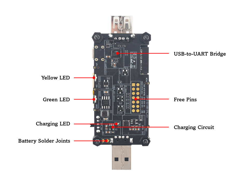
ESP32-S3-USB-OTG Bottom View (click to enlarge)
The following table starts with the Yellow LED on the left, and introduces the main components in the above figure in an anticlockwise order.
Main components |
Description |
|---|---|
Yellow LED |
Driven by GPIO16, set high level to turn on. |
Green LED |
Driven by GPIO15, set high level to turn on. |
Charging LED |
During charging, the red light is on, which will be turned off when charged. |
Battery Solder Joints |
3.6 V lithium battery can be welded to power the motherboard. |
Charging Circuit |
Used to charge lithium battery. |
Free Pins |
Idle pins that can be customized. |
USB-to-UART Bridge |
Single USB-to-UART bridge chip provides transfer rates up to 3 Mbps. |
Subboard: ESP32-S3-USB-OTG-SUB mount the 1.3-inch LCD screen
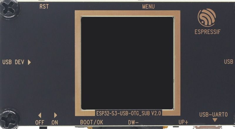
ESP32-S3-USB-OTG Subboard (click to enlarge)
Start Application Development
Before powering on the ESP32-S3-USB-OTG, please make sure that the development board is intact.
Required Hardware
ESP32-S3-USB-OTG
A USB 2.0 data cable (standard A to Micro-B)
Computer (Windows, Linux or macOS)
Software Setup
Please proceed to Get Started, where Section Installation Step by Step will quickly help you set up the development environment and then flash an application example onto your board.
Project Option
An example is provided for ESP32-S3-USB-OTG under the folder Examples .
You can configure project options by entering idf.py menuconfig in the example directory.
Contents and Packaging
Retail Orders
If you order a few samples, each board comes in an individual package in either an antistatic bag or any packaging depending on your retailer.
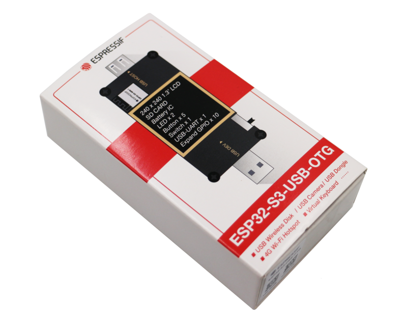
ESP32-S3-USB-OTG Package (click to enlarge)
Which contains the following parts:
Motherboard:
ESP32-S3-USB-OTG
Subboard:
ESP32-S3-USB-OTG_SUB
Fastener
Mounting bolt (x4)
Screw (x4)
Nut (x4)
For retail orders, please go to https://www.espressif.com/zh-hans/company/contact/buy-a-sample.
Wholesale Order
If purchased in bulk, the development board will be packaged in a large cardboard box.
For wholesale orders, please go to https://www.espressif.com/en/contact-us/sales-questions.
Hardware Reference
Block Diagram
The block diagram below shows the components of ESP32-S3-USB-OTG and their interconnections.
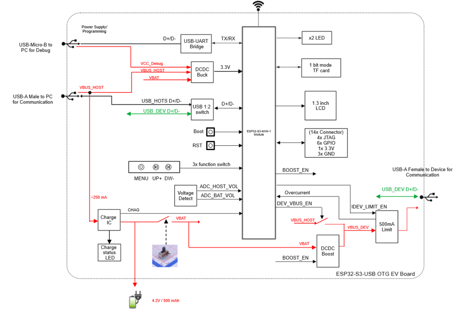
ESP32-S3-USB-OTG Block Diagram (click to enlarge)
Please note that the external interface corresponding to the USB_HOST D+ D- signal in the functional block diagram is USB DEV, which means that ESP32-S3 is used as a device to receive signals from other USB hosts. The external interface corresponding to the USB_DEV D+ D- signal is USB HOST, which means that ESP32-S3 acts as a host to control other devices.
Power Supply Options
There are three power supply methods for the development board:
Power supply through the
Micro_USBinterfaceUse the USB cable (standard A to Micro-B) to connect the motherboard to a power supply device, and set battery switch to OFF. Please note that in this power supply mode, only the motherboard and display are powered.
Power supply through the
USB_DEVinterfaceSet
DEV_VBUS_ENto high level, and set the battery switch to OFF. This mode can supply power to theUSB HOSTinterface. The lithium battery will be charged at the same time (if the lithium battery is installed)
Power supply through the battery
Set
BOOST_ENto high level, and set the battery switch to ON. You should solder a 1-Serial lithium battery (3.7 V ~ 4.2 V) to the power solder joint reserved on the back of the motherboard first. This mode can supply power to theUSB HOSTinterface at the same time. The battery interface description is as follows:

Battery Connection (click to enlarge)
USB HOST Interface Power Options
The USB HOST interface (Type-A female port) can supply power to the connected USB device. The power supply voltage is 5 V and the maximum current is 500 mA.
There are two power supply methods for the
USB HOSTinterface:Power is supplied through the
USB_DEVinterface, and the 5 V power is directly from the power source connected to the interface.Power is supplied through the lithium battery, and the 3.6 V ~ 4.2 V voltage of the lithium battery is boosted to 5 V through the Boost circuit. The working status of Boost IC can be controlled by BOOST_EN/GPIO13, set high to enable Boost.
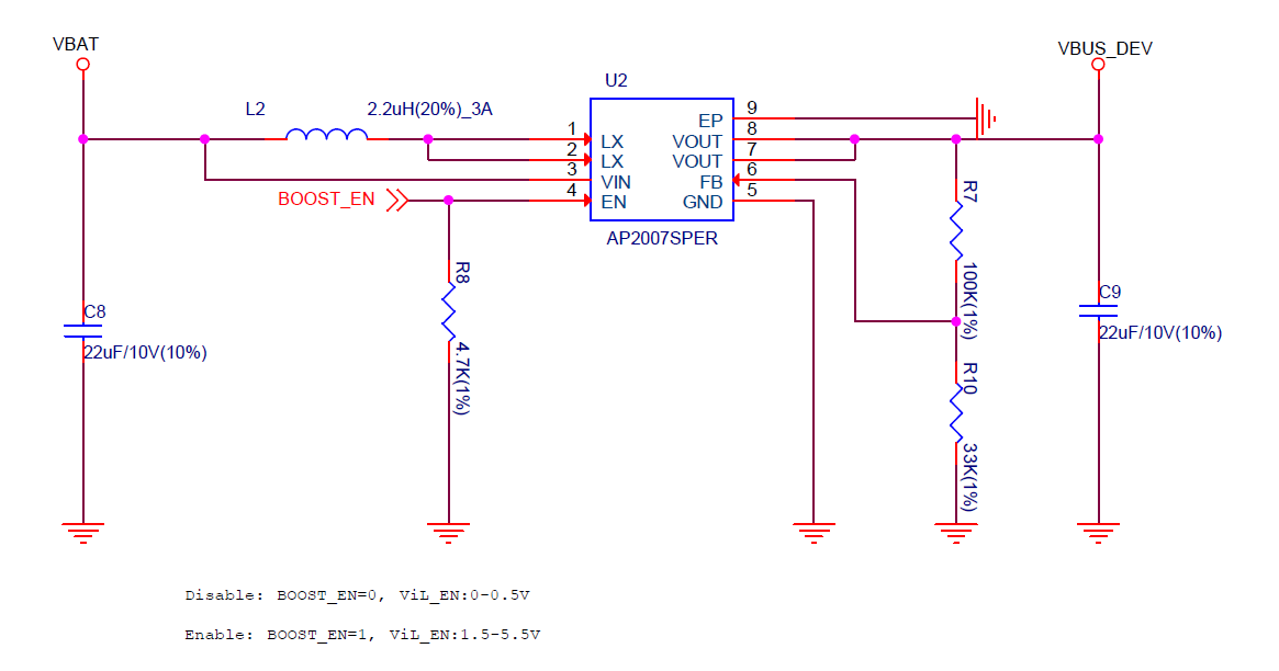
Boost Circuit (click to enlarge)
USB HOSTinterface power supply selection:
BOOST_EN |
DEV_VBUS_EN |
Power Source |
|---|---|---|
0 |
1 |
USB_DEV |
1 |
0 |
Battery |
0 |
0 |
No output |
1 |
1 |
Undefined |
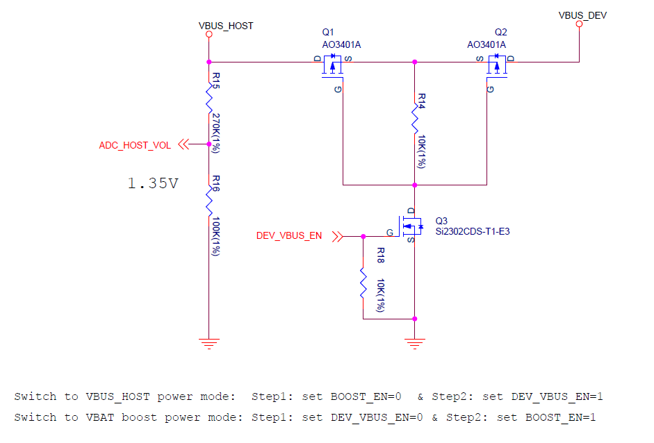
Power Switch Circuit (click to enlarge)
500 mA current limiting circuit:
The current limiting IC MIC2005A can limit the maximum output current of the
USB HOSTinterface to 500 mA. Please set theIDEV_LIMIT_EN(GPIO17) to high level to enable the current-limiting IC to output voltage.
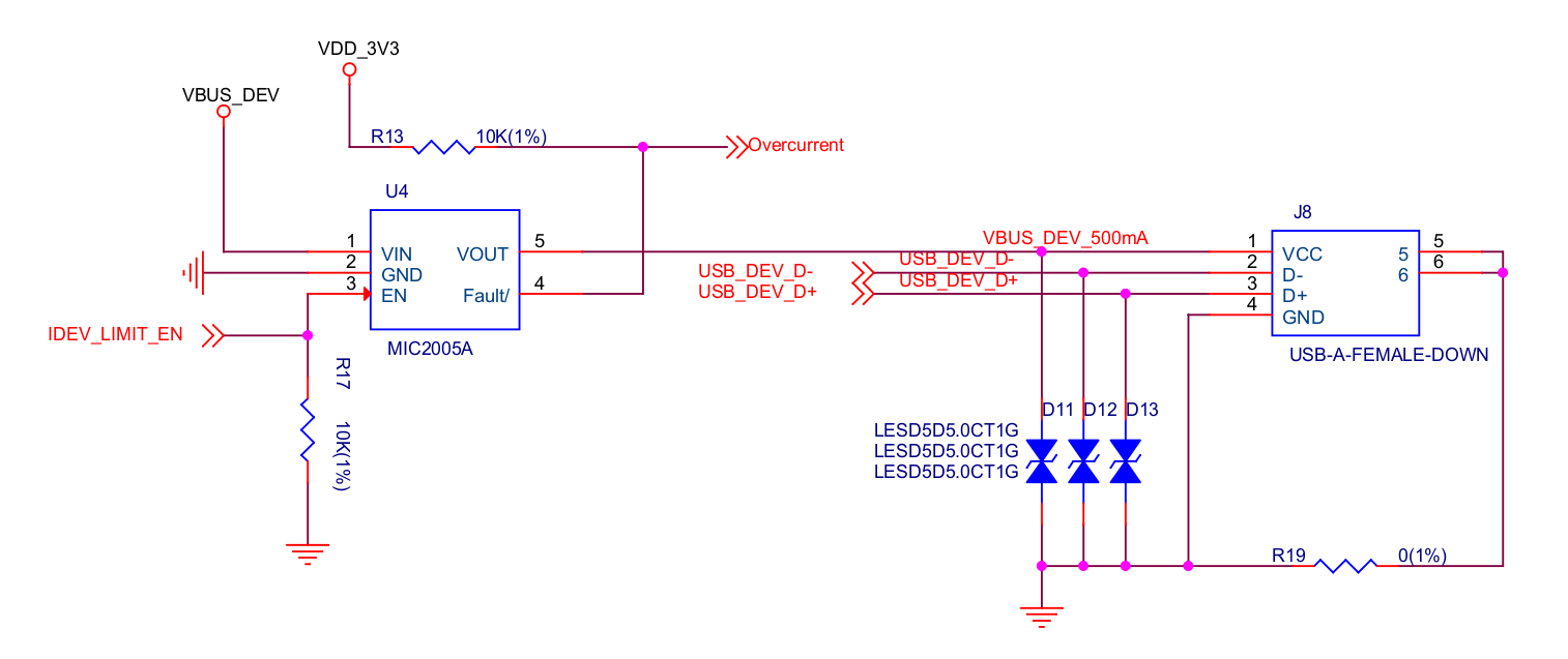
500 mA Current Limiting Circuit (click to enlarge)
USB Interface Switch Circuit
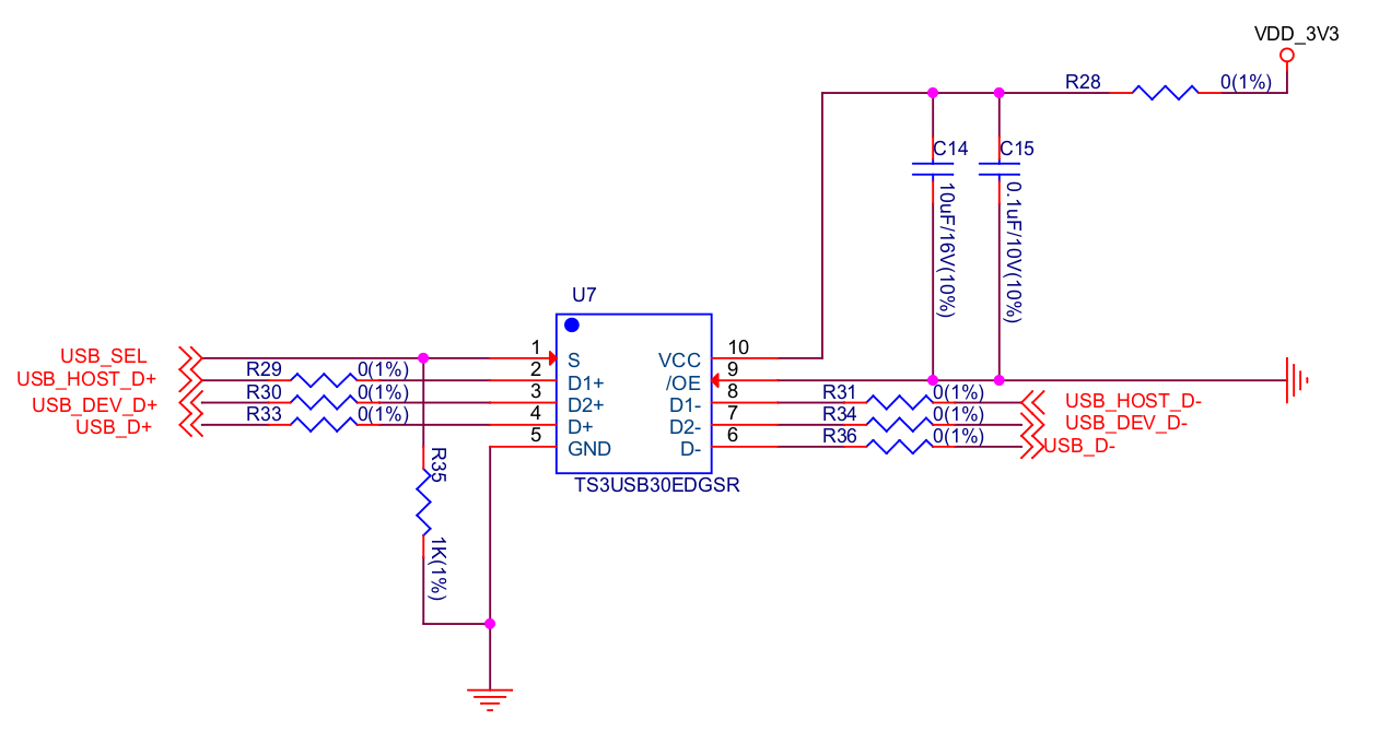
USB Interface Switch Circuit (click to enlarge)
When USB_SEL (GPIO18) is set to high level, the USB D+/D- Pin (GPIO19, 20) will be connected to
USB_DEV D+ D-. Then you can use theUSB HOSTinterface (Type-A female Port) to connect other USB devices.When USB_SEL (GPIO18) is set to low level, the USB D+/D- Pin (GPIO19, 20) will be connected to
USB_HOST D+ D-. Then you can use theUSB DEVinterface (Type-A male port) to connect to a host like a PC.USB_SEL is pulled low level by default.
LCD Interface
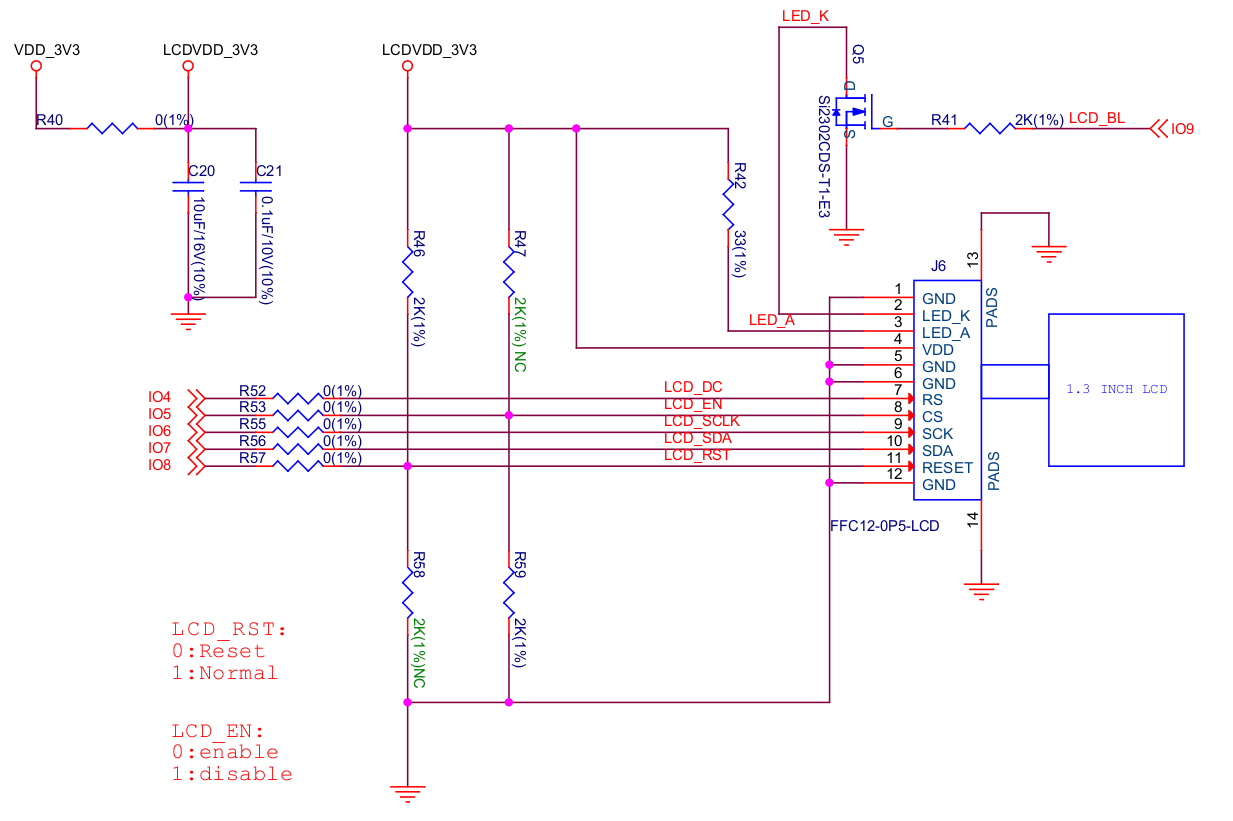
LCD Interface Circuit (click to enlarge)
Please note that this interface supports connecting SPI interface screens. The screen controller used by this development board is :dev-kits:` ST7789 <esp32-s3-usb-otg/datasheet/ST7789VW_datasheet.pdf>`, and LCD_BL (GPIO9) can be used to control the screen backlight.
SD Card Interface
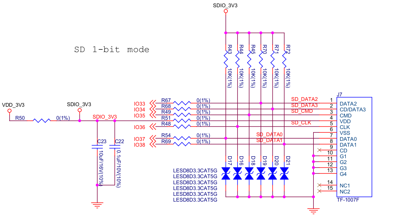
SD Card Interface Circuit (click to enlarge)
Please note that the SD card interface is compatible with 1-wire, 4-wire SDIO mode and SPI mode. After being powered on, the card will be in 3.3 V signaling mode. Please send the first CMD0 command to select the bus mode: SD mode or SPI mode.
Charging Circuit
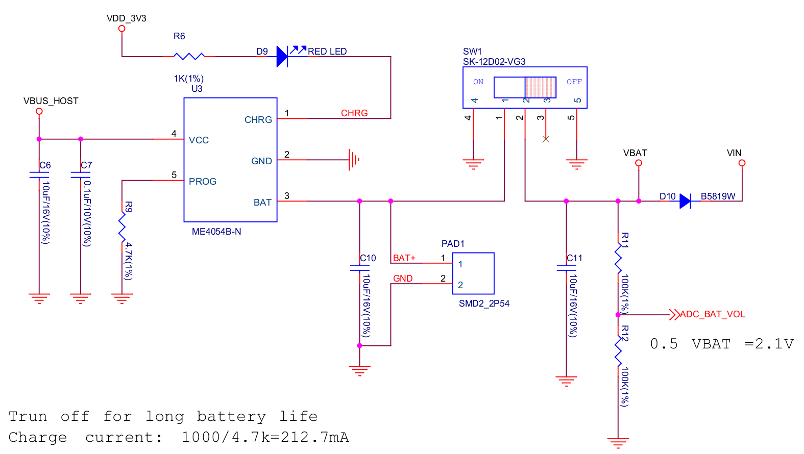
Charging Circuit (click to enlarge)
Please note that the Type-A male port can be connected to a power adapter that outputs 5 V. When charging the battery, the red indicator LED is on, after fully charged, the red indicator LED is off. When using the charging circuit, please set the battery switch to OFF. The charging current is 212.7 mA.
Pin Layout
Function pin:
No. |
ESP32-S3-MINI-1 Pin |
Description |
|---|---|---|
1 |
GPIO18 |
USB_SEL: Used to switch the USB interface. When high level, the USB_HOST interface is enabled. When low level, the USB_DEV interface is enabled. |
2 |
GPIO19 |
Connect with USB D-. |
3 |
GPIO20 |
Connect with USB D+. |
4 |
GPIO15 |
LED_GREEN: the light is lit when set high level. |
5 |
GPIO16 |
LED_YELLOW: the light is lit when set high level. |
6 |
GPIO0 |
BUTTON_OK: OK button, low level when pressed. |
7 |
GPIO11 |
BUTTON_DW: Down button, low level when pressed. |
8 |
GPIO10 |
BUTTON_UP: UP button, low level when pressed. |
9 |
GPIO14 |
BUTTON_MENU: Menu button, low level when pressed. |
10 |
GPIO8 |
LCD_RET: used to reset LCD, low level to reset. |
11 |
GPIO5 |
LCD_EN: used to enable LCD, low level to enable. |
12 |
GPIO4 |
LCD_DC: Used to switch data and command status. |
13 |
GPIO6 |
LCD_SCLK: LCD SPI Clock. |
14 |
GPIO7 |
LCD_SDA: LCD SPI MOSI. |
15 |
GPIO9 |
LCD_BL: LCD backlight control. |
16 |
GPIO36 |
SD_SCK: SD SPI CLK / SDIO CLK. |
17 |
GPIO37 |
SD_DO: SD SPI MISO / SDIO Data0. |
18 |
GPIO38 |
SD_D1: SDIO Data1. |
19 |
GPIO33 |
SD_D2: SDIO Data2. |
20 |
GPIO34 |
SD_D3: SD SPI CS / SDIO Data3. |
21 |
GPIO1 |
HOST_VOL: USB_DEV voltage monitoring, ADC1 channel 0. |
22 |
GPIO2 |
BAT_VOL: Battery voltage monitoring, ADC1 channel 1. |
23 |
GPIO17 |
LIMIT_EN: Enable current limiting IC, high level enable. |
24 |
GPIO21 |
0VER_CURRENT: Current overrun signal, high level means overrun. |
25 |
GPIO12 |
DEV_VBUS_EN: High level to enable DEV_VBUS power supply. |
26 |
GPIO13 |
BOOST_EN: High level to enable Boost boost circuit. |
Extended pin:
No. |
ESP32-S3-MINI-1 Pin |
Description |
|---|---|---|
1 |
GPIO45 |
FREE_1: Idle, can be customized. |
2 |
GPIO46 |
FREE_2: Idle, can be customized. |
3 |
GPIO48 |
FREE_3: Idle, can be customized. |
4 |
GPIO26 |
FREE_4: Idle, can be customized. |
5 |
GPIO47 |
FREE_5: Idle, can be customized. |
6 |
GPIO3 |
FREE_6: Idle, can be customized. |